
12. DESIGN OF EARTHFILL EMBANKMENT DAMS
This section deals with the design aspects of earthfill embankments. Where the site conditions and soil test results are favourable a safe and economical design for structures within the feasibility limitations set out in Chapter 10 can be achieved through careful application of the requirements specified below. In situations where the standard design requirements cannot be met or where the suitability of site or material conditions is uncertain, then specialised investigations and analysis and the services of a government approved dam design engineer, hydrologist and geologist/geotechnical expert will be required.
Any embankment dam must meet design requirements for stability under all conditions of construction and operation, and imperviousness, both through and beneath the embankment. This chapter examines the design required for earth-fill embankment dams which are widely used in Kenya. Rockfill dams are not discussed due to their limited utilisation in Kenya, primarily due to the difficulty in providing a robust impermeable membrane over a rockfill embankment.
12.1 Types of Embankment Dams
Earthfill embankment dams in Kenya are generally homogeneous or zoned embankments with a drainage blanket for internal seepage control for structures greater than 5 metres in height as shown in Figure 12-1 and Figure 12-2. The choice of whether to use a homogeneous or zoned embankment will be a function of the availability of suitable materials. Where there are limited quantities of impervious material, more pervious material can be placed on either side of the core creating a shell. The most economical type of dam will usually be the one for which materials can be found within the site or a reasonable haul distance.
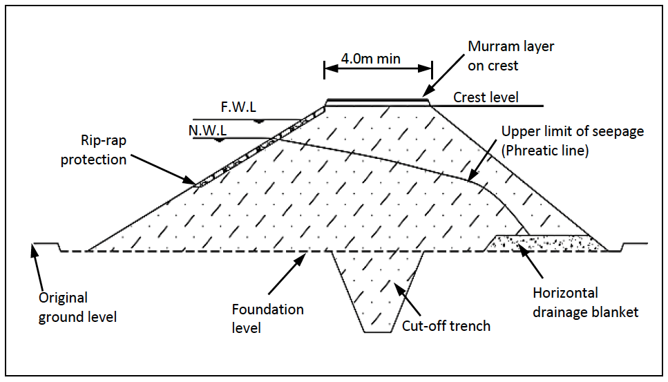
Figure 12-1: Homogenous Earthfill Dam with Drainage Blanket
Figure 12-2: Zoned Earthfill Dam
12.2 General Guidelines for the Design of Embankments
12.2.1 Design Criteria
The basic requirements for the design of an embankment dam are to ensure:
- Safety against overtopping. This is a function of the spillway capacity and freeboard;
- Stability. The stability of the slopes should be considered for the case of construction, steady state and rapid drawdown. Acceptable values for upstream and downstream slopes are provided in Table 12-3;
- Safety against internal erosion. The selection of material for the downstream shell and the design of internal drainage blanket and toe drain address this aspect;
- Functional performance in terms of excessive seepage. The design of the cut-off and impervious core address this aspect.
12.2.2 Dam Axis
The location of the dam axis should be chosen in such a way that the amount of fill required for the embankment is minimal. Usually the most appropriate location will be indicated by a narrowing of the contour intervals on the topographical map (see also Section 10.7).
The dam axis should normally be designed straight, unless special topographical features impose a curved axis.
Consideration should be given to the stability of the abutments and to avoid abrupt topographic discontinuities which can lead to differential settlement and shear cracks in the embankment.
12.2.3 Height of Embankment
The height of the embankment should be determined in accordance with the water depth calculated in Section 8.12 (Determination of the Required Storage Capacity) and then increased by the required gross freeboard (GF) which is a function of the width of the spillway; the wider the spillway, the lower the gross freeboard. This means that the final embankment height should be established through an iterative process which considers the cost of spillway excavation and the cost of embankment construction as the cost of the intake and other structures is constant irrespective of the height of the embankment.
An extra allowance or camber should be provided along the crest of earthfill dams, to ensure that the freeboard will not be diminished by post-construction settlement of the dam and the foundation. For small earthfill dams on relatively non-compressible foundations, a camber of about 2% of the embankment height (with a minimum of 0.20m) should be provided. Linear equations should be used to vary the amount of camber, and make it roughly proportional to the height of the embankment.
Figure 12-3 and Figure 12-4 show a diagrammatic cross-section and lay-out plan respectively of a small earth embankment.
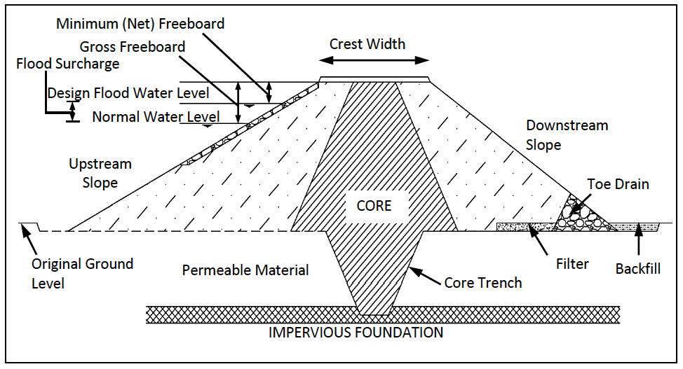
Figure 12-3: Cross Section of a Small Earth Dam
It should be noted that dam heights less than five metres be carefully considered as the freeboard is usually 1.00 – 1.50 metres and evaporation in arid areas is above 2.00 metres with the result that the effective storage available for use is less than is justified by the cost of the project.
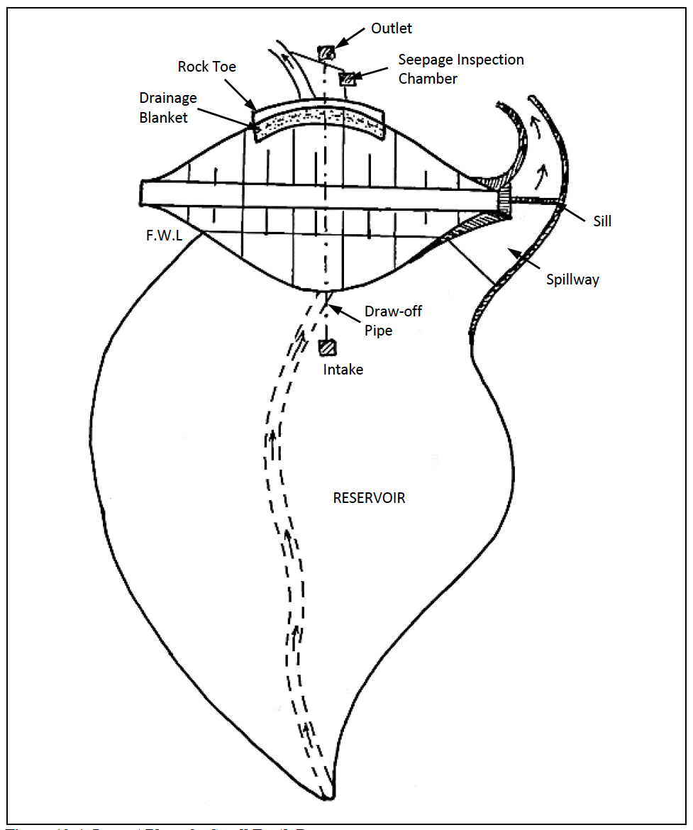
Figure 12-4: Layout Plan of a Small Earth Dam
12.2.4 Dam Freeboard
The embankment crest must be sufficiently higher than the maximum design water level in the dam to prevent any overtopping, including the possibility of waves washing up the embankment. The critical condition is when the inflow design flood (IDF) (for the design return period) is passing through the spillway. The net freeboard (NF) is defined as the minimum freeboard that occurs when the spillway is flowing at its maximum design flood capacity. The gross freeboard (GF) is therefore the minimum freeboard (NF) plus the water depth in the reservoir ($h_A$) above the spillway crest when the IDF is passing.
Equation 12-1
Where
The WRM Rules (2007) specify a minimum freeboard of 0.6m for Class A dams and 1.0m for Class B and C dams, unless otherwise specified by the WRMA. MoWI (2005) provides a relationship between fetch and minimum freeboard which has been summarised in Table 12-1. The more conservative value should be used. The water depth (hA) is established from the spillway design described in Section 12.3.
Table 12-1: Fetch and Minimum Freeboard
| Fetch (Km) | Minimum Freeboard (m) |
|---|---|
| 0 – 0.10 | 0.80 |
| 0.10 – 0.50 | 1.00 |
| 0.50 – 1.0 | 1.10 |
| 1.0 – 3.0 | 1.30 |
| 3.0 – 5.0 | 1.60 |
| > 5.0 | Reference should be made to publications for the required minimum freeboard |
12.2.5 Crest Width
The main criteria for crest width is related to construction and post-construction use of the crest, rather than slope stability. The crest width (CW) should therefore comply with Table 12-2. Consideration should be given to the camber and surface dressing of the crest. The crest should be sloped at 1% to shed rainwater. The crest should be dressed with a minimum of 200 mm of compacted murram or gravel. This provides a hardwearing surface that can handle periodic light traffic and is less likely to erode.
If the crest will not be used by traffic, it can be grassed which requires at least 200mm of top soil, lightly compacted, into which grass splits are planted. The grass species that are suitable are creeping (stoloniferous) grasses which cover the ground closely. These species include Kikuyu, Signal (Brachiaria humidicola), Bahia (Paspalum notatum), and Star (Cynodon spp) grass. Grass species that form tuffs should be avoided.
Table 12-2: Crest Widths
| Depth of Water (m) | Minimum Crest Width (m) | Comments |
|---|---|---|
| 0 – 3.0 | 3.00 | Note: minimum width for machinery access is 4.00 metres. A comfortable roadway width is 6 metres |
| 3.1 – 5.0 | 4.00 | |
| Greater than 5.0 | 5.00 |
12.2.6 Impervious Core for Zone Embankments
For dams of 5 - 15 metres high, where suitable soil is not available in sufficient quantities for constructing a homogeneous embankment, the construction of a "zoned" embankment can present a solution. In such cases a core of impervious material (generally clay) is incorporated in the embankment (See Figure 12-2), while more pervious fill material (a soil containing more sand than would normally be admissible) can be utilised for backfilling the shoulders of the embankment. The more pervious material on the downstream shoulder serves to lower the phreatic line to keep it within the embankment. A more granular material on the upstream also helps to reduce the uplift pressure under the embankment.
In the case of a zoned embankment, the impervious core should by designed with upstream and downstream slopes of 1.5:1 and should constitute at least 30% of the cross sectional area. The impervious core should penetrate through the cutoff trench to the impervious foundation layer. The top of the impervious core should exceed the flood water level.
12.2.7 Embankment Slopes
Embankment slope stability usually considers three critical conditions, namely:
- Sudden drawdown. This is a post-construction condition that assumes that the reservoir water level has dropped but the upstream face remains saturated;
- Sudden post-construction drawdown.
- Steady state. This assumes that the water level is at full supply level;
Embankment slope stability depends on the type of fill material used and on the height of the embankment. Analysis of the slope stability for different embankment heights and fill material has informed the recommended steepest slopes given in Table 12-3 for well compacted material.
Table 12-3: Recommended Slopes for Earth Embankments
| Embankment Height | Fill Material Type | Casing Slopes (h : v) | |
|---|---|---|---|
| Upstream | Downstream | ||
| < 5m | Well distributed granular/clay mix (GC, SC, CL) | 2.5 : 1 | 2.0 : 1 |
| 5 m to 10m | Well distributed granular/clay mix (GC, SC, CL) | 2.5 : 1 | 2.5 : 1 |
| 10 to 15 m | Well distributed granular/clay mix (GC, SC, CL) | 3.0 : 1 | 2.5 : 1 |
Incorporation of a clay-core does not affect the slopes of the embankment. However, in cases where particularly bad foundation conditions occur, it is advisable to select flatter slopes.
12.2.8 Embankment Foundation
The complete foundation area of the dam should systematically be cleared of all vegetation and topsoil containing organic matter including the removal of all logs, tree stumps, and unconsolidated material. Sand and/or silt from the river bed will also need to be cleared.
Adequate measures should be taken to eliminate steep slopes from the foundation area. No slopes steeper than 25% can be tolerated without special considerations. Steep slopes can create sliding planes through unequal embankment settlement against the original ground, thus creating seepage paths for water. Where steep river banks are encountered, these should be smoothed out as part of the foundation preparation work.
12.2.9 Core Trench
A core or cut-off trench is generally used to prevent seepage under the dam, by cutting off seepage paths through underlying pervious layers (see Figure 12-3). The core trench should extend up the abutments to the height of the normal water level.
The core trench should penetrate into impervious material by a minimum depth of not less than 1.00 metre. MoWI (2005) recommends a total core depth of 1/3 to ½ embankment height for economical reasons. However the project engineer should make a conscious decision regarding the depth of the core trench. The final excavation depth of the core trench will be determined once the core trench is fully exposed. However the estimated depth can be established based on test pit details. Note the depth of the core trench is generally not uniform because of additional excavation required at the intersection with the water course to ensure the impervious layer is fully penetrated. Alternative alignments should be considered if seepage under the embankment cannot be controlled.
The bottom width of the core trench is determined by the excavation width of the machines which are to be utilized (usually 1.5 times the machine width is normally accepted) with a minimum width of 3 metres.
The side slopes of the core trench should be a minimum of 1:1 or flatter in overburden or 1(h): 2(v) in soft/hard rock to provide sufficient contact between the core material and the undisturbed material and to reduce the likelihood of differential settlement causing tension cracks which create seepage flow paths. In addition, sufficient side slope enables proper compaction right up to the edge of the core-trench.
12.2.10 Grout Curtain
Dams placed on fractured rock may require treatment such as a grout curtain to minimise seepage below the embankment. The associated investigations, design and construction of a grout are not covered in this document. The reader is referred to other reference material for information on the investigations, design and construction of grout curtains and the services of a qualified geotechnical engineer will be required.
12.2.11 Filter Blanket and Toe Drain
A horizontal filter blanket and toe drain (see Figure 12-3 and Figure 12-4) are important for seepage control to capture the phreatic line within the downstream embankment and to relieve uplift pressures on the downstream side of the embankment. Filter blankets and toe drains are normally only used for dams exceeding 5 (five) meters in height.
The filter blanket must satisfy three design requirements:
- The filter material acts as a filter to prevents ingress of the embankment material into the filter;
- The filter material acts as a drain and should be sufficiently porous to alleviate seepage uplift forces and to drawdown the phreatic line;
- The filter should have sufficient capacity to convey the total seepage from both the foundation and embankment.
A horizontal drainage blanket is usually composed of clean river sand free from any organic matter. Ideally the filter blanket should consist of graded material (usually sand and graded ballast) and a toe drain which satisfies the recommended USBR filter criteria (United States Department of the Interior - Bureau of Reclamation, 1987). These criteria are:
Equation 12-2
Equation 12-3
Equation 12-4
Where
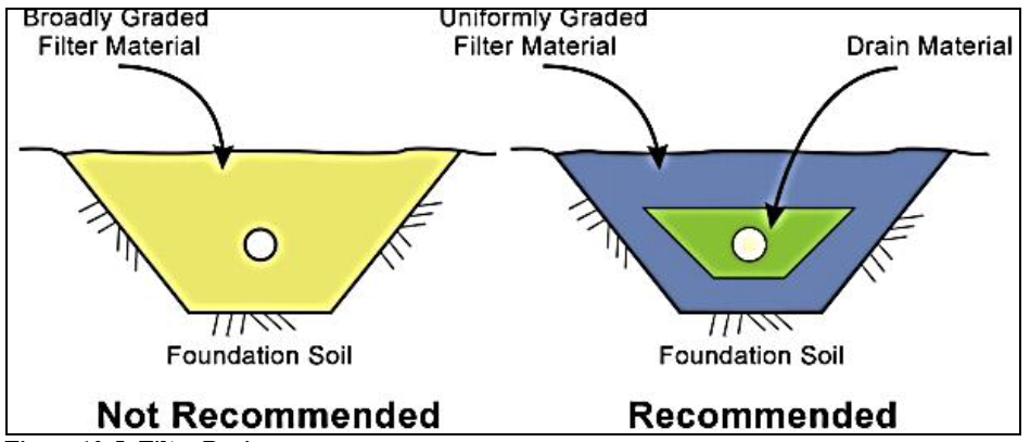
Figure 12-5: Filter drain
Synthetic geotextile membranes have been used as an interface to assist in meeting the particle size requirements for a graded filter. However, FEMA (2011) does not recommend the use of synthetic geotextile membranes where the membrane would be buried and its failure could compromise dam safety.
The thickness of the drainage blanket should not be less than 1.00 meter, while a width of at least 5.00 meters is recommended. The drainage blanket should be extended up to an elevation of 4 to 5 meters below the embankment crest. The position of the drainage blanket within the embankment cross section should be such that there is at least one metre of material on top of the blanket at the downstream point (as shown in Figure 12-3). The drainage blanket is typically placed horizontally on the foundation surface. However, alternative geometry, alignments and placements should be considered where there is concern regarding potential seepage paths beneath the core trench or within the abutments.
A toe drain consisting of graded ballast placed against or below the drainage blanket can be used to increase drainage capacity. A perforated pipe (e.g. perforated corrugated HDPE pipe), acting as a collector drain, is placed within the toe drain to convey seepage water away from the embankment. The collector drain should pass through a chamber where seepage flow rates can be observed and monitored. Care should be taken during construction to avoid crushing the pipe drain.
12.2.12 Rock Toe
A rock toe, composed of variable size rip-rap (25 – 250mm) can be placed along the groin of the embankment to protect the embankment against erosion. The rock toe can be 1 metre in height and placed at a 1.5 (h): 1(v) slope. The rock toe is distinguished from the toe drain which has graded material designed to convey seepage water away from the embankment.
12.2.13 Upstream Slope Protection
In cases of long reservoirs (fetch > 500m) a protective layer of hand placed rip-rap (rubble stone/hardcore) should be placed on the areas of the upstream embankment slope which are likely to be affected by the wave action. This zone is usually 0.6 metres above the normal water level to 2/3 of the water height. The thickness of the rip-rap layer should not be less than 0.30 metres. A gravel blanket (min 150mm) will normally be provided under the rip-rap layer. The bottom toe of the rip-rap layer needs to be keyed into the embankment face to prevent gradual movement of the rip-rap down the slope. This can be achieved by the construction of a step or inset at the appropriate height along the embankment face. The space between the top line of the rip-rap and the crest can be grassed to reduce erosion.
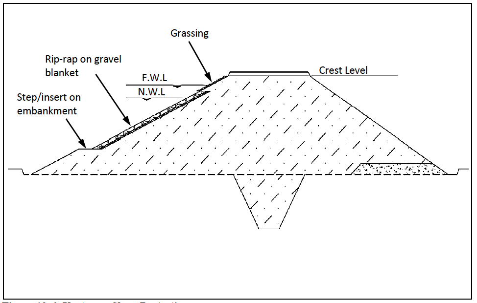
Figure 12-6: Upstream Slope Protection
12.2.14 Downstream Slope Protection
The best form of erosion protection for the downstream face is a good cover of creeping grass (e.g. Kikuyu, Signal (Brachiaria humidicola), Bahia (Paspalum notatum), and Star (Cynodon spp) grass). Grass species that form tuffs should be avoided. In order to obtain a good grass cover, a layer of top soil (200 – 400 mm thick) is placed on the downstream face. This requires particular attention during construction to schedule stockpiling of top soil and inclusion of the top soil along the downstream face during the construction process.
12.3 Design of Spillway Structures
The function of the spillway is to discharge the normal and flood flows safely around the embankment and back to the water course without compromising the long term functionality and integrity of the dam.
12.3.1 Location and Type of Spillways
The common type of spillway used with earth embankments is a side channel spillway, excavated in earth or rock next to the embankment. The incorporation of relatively large concrete structures as spillways for small earth dams is difficult to justify on economical grounds.
The basic factors to be taken into account when choosing a spillway location are:
- The spillway should be kept away from the embankment in order to avoid the need for concrete protection structures, and
- Excessively steep valleys should also be avoided, in order to prevent erosion problems in the spillway channel and to reduce excavation volumes.
Consequently spillways are usually located on the side of the embankment where the valley slopes are flattest. In the case of large discharges to be catered for, the possibility of constructing two spillways -one on either side of the embankment- can be considered; the quantity of excavation required usually being the decisive factor. In cases where the topography of the site favours such a solution the possibility of discharging the flood waters into a valley other than the original river valley can also be considered. This could however have adverse effects on eventual water users downstream of the dam and on the flow regime of the other river.
Because of the cost of rock blasting, extensive excavation in rock should be avoided, but the location of the spillway channel on a relatively horizontal layer of bedrock is wherever possible a handsome solution to all erosion problems in the spillway channel. Problems with spillway channel erosion prohibit the construction of spillways on backfilled soil. Spillways should always be excavated in original material.
It is always preferable to let spillway channels discharge on bedrock. Where this is not possible, it is advisable to protect the river-bed from scouring at the location of the spillway discharge. Lining with reno-mattresses, gabions or pitched stone is usually appropriate.
Only side channel spillways excavated in earth or rock will be considered. For all other types of spillways, reference is made to the United States Department of the Interior - Bureau of Reclamation, 1987. A site may require a side spillway on both sides of the embankment.
The side spillway normally consists of three parts: Inflow Section, Control and Outflow Channel (see Figure 12-7) and Drawing Type III in Appendix B.
Figure 12-7: Spillway Design
12.3.2 Control Section
The normal water level in the reservoir is controlled by the height, length (i.e. width of spillway channel) and geometry of the spillway sill. The sill level is controlled by a reinforced concrete sill (minimum width 300 mm), thus preventing lowering of the crest level by erosion. This sill is usually aligned with the dam axis. The depth of the sill (minimum 1.00 m) below ground level should be determined by the engineer to minimise seepage underneath the sill. Where the sill is proud of the spillway bed and there is a risk of erosion and undercutting of the sill, a 150 mm thick reinforced concrete apron should be placed downstream of the sill. The width of the control section should be a minimum of 10 m unless a detailed analysis justifies otherwise.
Consideration should be given to the likelihood of erosion along the spillway floor and side slopes, particularly in the control section. Grouted masonry can be laid along the floor and side slopes to protect against erosion where the spillway is cut into soil and where a good grass cover cannot be guaranteed.
12.3.3 Inflow Section
The inflow section leads the flood water to the control section. Usually, it slopes moderately (maximum 1 %) upwards to the sill. The cross-section is usually narrowed down gradually towards the sill. Care should be taken that the water flowing to the control section remains far enough from the earth embankment to minimise the risk of erosion of the embankment face.
12.3.4 Outflow Channel
The outflow channel discharges the flood water back into the riverbed at acceptable velocities that do not cause erosion. For spillways excavated in undisturbed earth, a maximum velocity of 2.5 m/s is usually acceptable under Kenyan conditions. Control of the outflow channel water velocity is usually achieved through adequate slope selection. Otherwise lining of the channel (or parts thereof) with rip-rap will be required. In such cases velocities up to 6-7 m/s can be accepted. In case of unacceptably long outflow channels, the possibility of incorporating a gabion or concrete drop structure can offer a solution. The Manning formula (Equation 12-5) can be used to establish the velocity in the outflow channel for different gradients, widths and channel roughness.
Recommended values for outflow channel slopes are presented in Table 12-4.
Table 12-4: Recommended Values for Outflow Channel Slopes
| Type of Soil | Slope (%) |
|---|---|
| Earth | <0.5 |
| Murram | 0.5 – 1 |
| Hard rock | 1 - 2 |
Consideration should be given to the velocity of the water as it re-enters the water course as this can create unwanted erosion of the river bank. There are various options to reduce the speed of flow including changing the slope to induce a hydraulic jump, creating a stilling basin or placing chute blocks in the line of flow. Reference should be made to detailed design documents where energy dissipaters are required. Energy dissipaters should not impede flow through the control section.
12.3.5 Training Walls for Control and Outflow Channel
Training walls are required if the control and outflow channels are cut into soil to prevent erosion of the channel side walls. The height of the training wall should exceed the flood water level. A masonry wall, anchored on a secure footing, with appropriate buttresses, is acceptable for heights less than 2 m. A reinforced concrete retaining wall is required for wall heights above 2 m. Well constructed gabions are feasible where wall heights are less than 1m. The services of an engineer should be engaged to establish the full design for a reinforced concrete retaining wall.
12.3.6 Return to Water Course
The point at which spillway flows join the water course should be examined and protected against erosion that may occur if high velocity flows are expected. Maintaining well vegetated river banks, or placing well constructed gabion boxes, are options to minimise river bank erosion. See also the discussion on options for reducing flow velocities in Section 12.3.4.
12.3.7 Determining the height, width and slopes of the spillway
The design of the spillway determines the water level in the reservoir or approach height ($h_A$). There are two conditions that can apply:
- Flow in the outflow section is supercritical and the spillway sill acts as a broad crested weir and therefore the sill controls the approach height;
- Flow in the outflow section is subcritical and the depth of flow in the outflow channel controls the approach height.
It is therefore important to determine which condition applies or to design the spillway width and slopes so that the selected condition applies.
Typically the design of the spillway aims to ensure that the first condition applies i.e. the spillway sill controls the flow and level of water in the reservoir. This is achieved by ensuring that:
- The capacity of the outflow section exceeds the capacity at the control section;
- The flow condition in the outflow channel is supercritical. For channels excavated in soil (n = 0.025) this implies a gradient of more than 0.75% (0.0075);
- The depth of water in the outflow channel is less than the depth of flow over the sill.
When these conditions are met, the sill in the control section will act as a broad crested weir.
Flow characteristics in the outflow channel will correspond to the Manning equation as shown in Equation 12-5.
Equation 12-5
Where
Table 12-5: Manning n Values for Typical Spillway Channel Material
| Type of channel and material | Minimum n value | Normal n value | Maximum n value |
|---|---|---|---|
| Concrete lined | 0.015 | 0.017 | 0.02 |
| Masonry line with cemented rubble | 0.017 | 0.025 | 0.03 |
| Straight, uniform channel excavated in clean earth | 0.018 | 0.022 | 0.025 |
| Straight, uniform, earth channel with short grass, few weeds | 0.022 | 0.027 | 0.033 |
| Straight, uniform, earth channel not maintained with dense weeds | 0.05 | 0.08 | 0.12 |
| Rock cut – smooth and uniform | 0.025 | 0.035 | 0.04 |
| Rock cut – jagged and irregular | 0.035 | 0.04 | 0.05 |
(Source: Chow (1959))
The water depth corresponding with the Manning equation (the " normal depth" $h_N$ which will occur at sufficient distance downstream from the sill) may be determined by writing the Manning equation in terms of discharge as shown in Equation 12-6.
Equation 12-6
Where
When supercritical flow occurs in the outflow channel, the sill (control) will basically play the role of a weir, and the water depth over the sill will be equal to the critical depth $h_C$. The depth of approach $h_A$, will then be 1.5 times the critical depth as shown in Equation 12-7. Table 12-6 presents values of approach depth for a range of unit discharge values (q).
Equation 12-7
Where
Table 12-6: Values of q and $h_a$
| q [/s/m] |
[m] |
[m] |
|---|---|---|
| 0.25 | 0.28 | 0.19 |
| 0.50 | 0.44 | 0.29 |
| 1.00 | 0.70 | 0.47 |
| 1.50 | 0.92 | 0.61 |
| 2.00 | 1.12 | 0.74 |
| 2.50 | 1.29 | 0.86 |
| 3.00 | 1.46 | 0.97 |
| 3.50 | 1.62 | 1.08 |
| 4.00 | 1.77 | 1.18 |
| 4.50 | 1.91 | 1.27 |
| 5.00 | 2.05 | 1.37 |
| 5.50 | 2.18 | 1.46 |
| 6.00 | 2.31 | 1.54 |
| 6.50 | 2.44 | 1.63 |
| 7.00 | 2.56 | 1.71 |
| 7.50 | 2.68 | 1.79 |
| 8.00 | 2.80 | 1.87 |
| 8.50 | 2.92 | 1.95 |
| 9.00 | 3.03 | 2.02 |
| 9.50 | 3.14 | 2.10 |
| 10.00 | 3.25 | 2.17 |
For supercritical flow conditions, the normal depth of flow in the outflow channel ($h_N$) is smaller than the critical depth ($h_C$).
If $h_N$ is greater than $h_C$ the flow in the outflow channel is subcritical, and the depth of approach $h_A$ will depend of the water velocity and height in the outflow as in Equation 12-8.
Equation 12-8
Where
The procedure for spillway design is an iterative process that can follow the sequence described below:
For the inflow design flood (Q), use:
- Equation 12-7 to test different values of sill length (L) to determine an acceptable approach height ($h_A$), noting Equation 12-1 that determines the gross freeboard (GF) and the final embankment crest elevation;
- Select trial widths and slopes for the outflow section and use Equation 12-6 to establish the depth of flow ($h_N$);
- Check that flow conditions in the outflow channel are supercritical and that the flow depth in the outflow section ($h_N$) is less than the flow depth over the sill ($h_c$);
- Check that flow velocities are acceptable (less than 2.5 m/s for earth channels, less than 6 m/s for rock lined channels).
12.3.8 Construction Details
Basic construction details for earth channel side spillways are outlined in Appendix B (Type Drawing II - Spillway for Small Earth Dam).
The spillway alignment is usually curved to keep the spillway away from the embankment.
The side slopes of an earth channel spillway should be decided as a function of the material in which the spillway is excavated. Side slopes of 1:1 (for shallow spillways excavated in firm material) to 3:1 (for deep spillways excavated in soft soil) are possible. Spillways should always be excavated in original undisturbed material.
Concrete sills can be constructed at various locations in the outflow channel. Their essential function is to fix the spillway level and act as an erosion barrier. At the spillway crest, the construction of a concrete sill is imperative. Concrete sills should also be constructed where changes of the slope in the outflow channel occur.
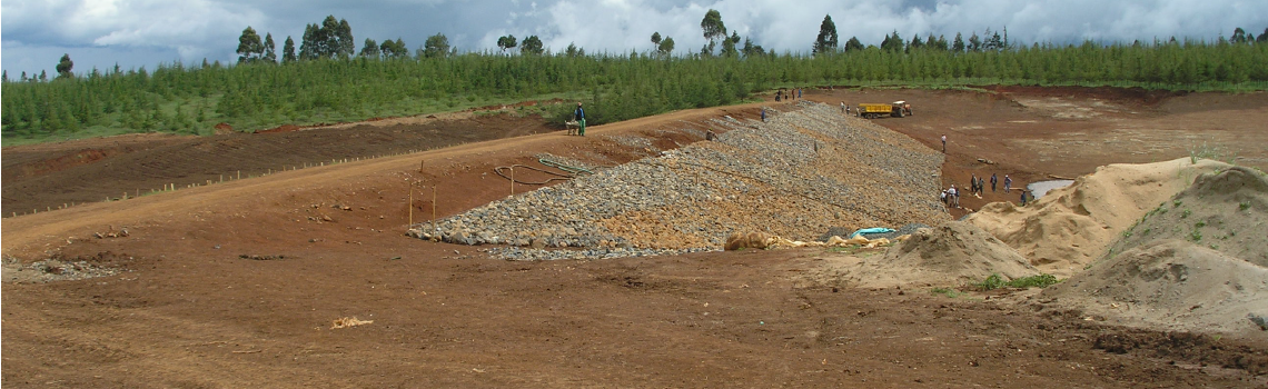
Where soft materials or excessive velocities occur in parts of the spillway, a lining with angular rip-rap (made of solid rock and least 0.30m thick) can provide a solution. This rip-rap layer should be provided with an underlying gravel layer, and should be compacted.
Wherever run-off water from the valley slopes is expected to flow into the spillway channel in substantial quantities, the construction of a spillway protection trench (cut-off drain) is recommended. Construction details for this trench are given in Appendix B -Type Drawing II.
12.3.9 Trickle Spillway
A trickle spillway is required where there is likely to be a fairly continuous flow over the spillway. A continuous flow can cause steady erosion along the spillway bed leading to rills and potentially gullies that can threaten the integrity of the dam.
The options for a trickle spillway are:
- Low section in the spillway sill that directs flow into a lined channel (masonry, concrete, etc). This low section of the sill and the lined channel should be placed along the outside edge of the spillway to keep any risk of erosion or seepage away from the embankment;
- Pipe (GI, PVC, HDPE) at normal water level, placed through the concrete sill and buried along the outside edge of the spillway. The pipe is vulnerable to being washed out by the flood flows and so should be properly buried, anchored and protected;
- If the flows warrant, then a culvert can be used to convey continuous discharges along the outside edge of the spillway.
In the event that the normal flows exceed the options above, then other options (e.g. concrete lined spillway, drop-inlet spillway) may be required and the reader is advised to refer to other publications on the topic.
12.4 Design of Draw-Off Works
Due to the risk of pollution of the reservoir from human or livestock contamination, it is preferable to provide a draw off system that delivers water below the dam. However, a draw off system can create a seepage flow path that can compromise the integrity of the embankment unless designed and constructed properly. Consequently the additional cost and construction complications may outweigh the benefits of a draw-off system through the embankment for a small dam.
The design of the draw off system should consider:
- Peak flow requirements to satisfy water demand;
- Variable water level in the reservoir;
- Risk of debris and blockages in the pipe;
- Minimum flow velocities (0.6 m/s) and minimum size of pipe (50 mm dia.) to ensure these are self-cleaning;
- Need to regulate the discharge in the drawoff pipe.
If the draw-off system is also being used to release compensation flows for downstream water rights, then this requirement should also be factored in to the design of the draw-off system.
A typical draw-off system consists of an intake at the bottom of the reservoir with a draw-off pipe passing through the embankment or foundation. This pipeline is then connected to a pump house or valve chamber (Figure 12-8) from where water will usually be provided to the distribution system and consumer points. Provision for compensation flows to safeguard downstream water-rights can also be made from this structure.
If the draw-off works are intended to pass normal river flows then a drop inlet concrete structure may be more appropriate with concrete culvert of sufficient capacity to convey the required flows. Reference should be made to alternative detailed design documents for the design of a concrete drop inlet structure and concrete culverts.
Figure 12-8: Typical Outlet Works for a Small Earth Dam
Type Drawings III, IV and V given in Appendix B show construction details for intake, draw-off pipe, valve chamber (III) as well as cattle trough (IV) and communal water point (V) for small earth dams.
12.4.1 Intake Structure
The intake structure will generally consist of a concrete anchor block supporting a vertical perforated galvanised steel pipe. Plastic pipes should not be used since they tend to degrade in the sun during periods when low water levels occur. The pipe upstand can be surrounded by a protective steel structure or a cone of rubble stone and large diameter gravel which serves to protect the upstand from debris, livestock, wildlife and vandalism (See Type Drawing III).
The pipe diameter is typically 100mm in order to decrease the risk of the pipe getting blocked. The perforations on the upstand, starting above the expected silt level, should be at least 12mm diameter and should constitute at least 10% of the surface area of the pipe. The flanged joint for the upstand should be above the concrete anchor block. This means that the upstand can be replaced if needed without damaging the anchor block. However, this introduces a risk of vandalism or theft of the upstand when the reservoir is dry.
In the event that a rough filtration system is desired to improve water quality for public use, it is possible to lay a 30 metre long perforated pipe at an inclined slope (1%) within a graded filter as shown in Figure 12-9. In general, treatment facilities, if needed, should be provided on the downstream side of the embankment where routine maintenance of the treatment works can be undertaken.
12.4.2 Draw-Off Pipe
The draw-off pipe(s) should have a minimum diameter of 100mm, in order to decrease the risk of the pipe getting blocked by debris or silt. The pipe can be galvanised iron, uPVC (Grade E), or HDPE.
As the draw-off pipe forms a preferential seepage path, it should be situated on firm ground preferably below the foundation level of the embankment. Anti-seep collars should be provided at regular intervals (e.g. one per every six metre pipe length) so that the length of the potential flow path is increased to at least 115% the length of the pipe.
There is a risk that the pipe can be damaged by the construction activities as the embankment is being built. Consequently, the trench for the draw-off pipe should be at least one metre below the construction working surface. In order to minimise the risk of damage to the pipe, the pipe itself should be surrounded with concrete.
Where the pipe is not being placed in a concrete surround, a compacted bentonite/soil mix (50 Kg bentonite to one cubic metre of soil) is recommended along the entire trench to minimise the chance of seepage.
It is not recommended to put a control valve on the upstream side of the draw-off pipe. In general accessing the valve for regular maintenance is not possible.
Type Drawing III shows a typical arrangement for the draw-off pipe and intake.
Figure 12-9: Graded Filter for Public Water Point Intake
12.4.3 Outlet Works
The outlet works usually consist of a pump house or valve chamber at or below the downstream toe of the embankment where fittings are placed on the draw-off pipe for purposes of controlling and directing the flow. The arrangement of pipe, tees and valves should allow water to be directed to the consumer points and allows flushing of the draw-off pipe to remove any sediments. The pipe and fittings should be securely anchored to ensure that the action of opening and closing the valves does not result in any movement of the pipe.
12.5 Design of Scour or Compensation Flow Arrangements
Scour is the flushing of sediments from the reservoir area. In general for the type of dams under consideration, a scour outlet to allow flushing of sediments from the reservoir is not foreseen. Sediments tend to settle and then consolidate and so the effectiveness of a pipe to draw out the sediments is questionable. Other forms of de-silting a reservoir should be pursued.
A compensation flow pipe can be included in the design. This is essentially a second draw-off pipe albeit for a different purpose and should therefore follow all the design requirements of the draw-off pipe. However, the inlet structure can be a bell-mouth pipe inlet surrounded by a steel cage (to prevent ingress of large debris). The compensation flow pipe should also emerge into a pump house or valve chamber in which control fittings are placed.
12.6 Long Term Monitoring of Embankment
The long term behaviour of an embankment should be monitored for early detection of any problems. Options are outlined in Table 12-7. These will require ancillary structures to be placed at the end of the construction period.
Table 12-7: Options for Long Term Monitoring of Embankment
| Aspect to be monitored | Options for Monitoring |
|---|---|
| Settlement | Bench marks placed at end of construction along crest. These are surveyed periodically with reference to the site datum to detect changes in elevation of the crest. |
| Alignment | Bench marks along crest aligned in a perfect straight line. Periodic checking of alignment of bench marks will help detect any shift in embankment alignment. |
| Seepage | Seepage through the embankment should be captured in the filter drain and conveyed via the drain pipe away from the embankment. The discharge and turbidity of the seepage water should be monitored. This can be achieved by placing a v-notch weir or flow meter on the seepage water. |
The placement of piezometers to detect the phreatic level within the embankment is not generally expected for small earthfill dams. However, close attention should be given to the point of emergence of seepage water, if any, on the downstream face, and remedial measures taken to contain the phreatic line within the embankment and directed to the drainage blanket.
12.7 BoQs, Specifications and Reporting
A design report format is provided in Chapter 19. Sample BoQs and specifications are also available on the complementary website.
Construction techniques can vary from contractor to contractor and it is important to have close collaboration between the dam owner, the contractor and the construction supervisor to make sure that the final product meets or exceeds the design specifications and requirements.
12.8 Construction
12.8.1 Construction Team
Assuming mechanized construction, a typical construction team will consist of a foreman, several drivers and a selection of manual labourers. A site engineer or construction supervisor will also be present.
The foreman’s role is to oversee the workers, to plan the construction activities and to ensure that materials (including fuel, water, etc) are available as needed for the construction activities. The foreman and the site engineer/construction supervisor will always need to work closely together.
Drivers for the various machines will be needed. Drivers should have suitable experience with their machinery and with similar projects.
Manual labour will always be required in construction of earth embankments. Labour for removal of stones, roots and organic materials are needed throughout construction. Manual labour is essential for piping tasks and for concrete work on pipe surrounds and spillway sills.
The site engineer will be responsible for checking or setting out the initial layout out as needed and for carrying out all supervision activities.
12.8.2 Personal Protective Equipment
Occupational Safety and Health Act, No. 15 of 2007 and revised in 2010, provides for the safety, health and welfare of workers and all persons lawfully present at workplaces, which includes construction sites. The Act also requires that in workplaces where employees are exposed to wet or to any injurious or offensive substances, the employers must provide and maintain clothing and appliances that are adequate, effective and suitably protective. Such equipment includes:
- Helmets/ hard hats;
- Gloves;
- Reflector jackets;
- Goggles;
- Sound mufflers;
- Hard-nosed boots.
12.8.3 Schedule of Works
As dam construction must normally be scheduled with regard to expected rains, it is important to develop an accurate and attainable schedule of works before construction begins. Figure 12-10 shows an elaborate example of a bar chart construction schedule for the construction of a new dam. A construction plan should be prepared at the start of construction and used to evaluate progress. If construction work does not follow the planned schedule it should be noted why this is so.
Figure 12-10: Construction Schedule for Small Earth Dam
12.8.4 Embankment Work
The main items which should receive attention during the construction of the embankment are the foundation and the compaction of the fill.
-
Setting Out: With the help of the appropriate bench marks, the centre-line of the embankment, embankment area, spillway area and the F.W.L. (delimitating the maximum impounded area) will be demarcated. During the construction of the embankment, width and height of the embankment will be set out at least every metre, preferably using wooden pegs with fill levels indicated by painting.
Calculations for setting out are shown below. Equation 12-9 shows the typical information needed for setting out embankment toes.
Once the centreline has been established, the most important layout work is to locate the toes of the embankment. The toe position is determined by the elevation of the working surface and can be calculated as a distance from the centreline.
Equation 12-9
$\mathbf{D = 0.5 CW + S \times (CH - GE)}$
Where:
D is the horizontal distance from the centreline to the toe in m;
CW is the crest width in m;
S is the embankment slope in m/m (i.e. 3 for a 3H to 1V slope);
CH is the final crest elevation in m;
CE is the ground elevation in m.To layout, the ground elevation is measured at the approximate toe position and the distance D is calculated. This is then measured off and the ground elevation is taken again. D is recalculated and re-measured and the ground elevation is taken again. This is repeated until the measured distance D agrees with the calculated distance D for the elevation at the toe peg.
-
Foundation Preparation: The whole area of the embankment should be cleared of loose rocks, trees, tree roots and other vegetation and should be" stripped" of top-soil up to a depth not less than 0.30 m below the natural ground level. The resulting spoil can be stock-piled for re-use as topsoil for covering the downstream slope of the embankment before grassing.
The reservoir area should be cleared of all vegetation below full supply level. Grass may be left in place, but bushes, trees and tree roots must be completely removed. The borrow areas should be stripped in the same way as the embankment area.
-
Core Trench and Embankment Construction: During excavation of the core trench the information obtained from the test pits should be checked. If required, at this stage, the depth of the core trench can be modified in accordance with the findings during the excavation.
For the actual construction of the embankment it is preferable to use earth moving equipment and heavy mechanical compactors, since it is extremely difficult to achieve acceptable standards of compaction by labour intensive methods. Furthermore, it is worth noting that manual labour can achieve about 2 $m^3$ of fill per day per person, which means that 10,000 man-days are required for the construction of an embankment of 20,000 $m^3$. A typical mechanized operation can normally place and compact between 300 to 800 cubic meters of material per day which would then take between 25 to 67 days.
The actual embankment construction should be carried out by spreading soil in 0.15 m to 0.20 m layers, watering in order to approach the optimum water contents and compacting to achieve the specified density. Scarifying should take place at least once every morning, in order to assure proper adherence between new layers and layers from the previous day.
Note that failure to work at Optimum Moisture Content (OMC) will not deliver the Maximum Dry Density (MDD).
Depending on the compaction equipment being used, slightly thicker layers (up to 0.3m) can be placed but care must be taken to ensure that any water applied to the spread material penetrates throughout the entire layer and that the required density is achieved throughout the layer.
Some contractors also prefer to water the material during borrow excavation so that once it is spread it is already at a moisture content that will allow proper compaction. This method ensures a more uniform moisture content throughout the layer.
-
Compaction Control: Some form of compaction control during the construction should always take place. A minimum compaction of 95 % of the maximum dry density of the BS Proctor test (2.5 kg rammer) is required. Proper field density tests can unfortunately only be carried out if experienced laboratory personnel and equipment are available. If this is not the case, a rudimentary method of compaction control is to try to re-excavate a fill by hand: in case excavation of the fill is only possible by means of a hoe (jembe) an acceptable degree of compaction has been achieved. In cases where fairly easy excavation by shovel is possible, the compaction is insufficient.
-
Construction Period: It is always preferable to complete construction of a dam during one dry season. A partially filled embankment without adequate temporary flood diversion works has the risk being washed away by the floods. In case it is impossible to avoid the rainy season during the construction period, it is advisable to design and construct appropriate flood diversion works.
-
River Diversion: The simplest way to provide a river diversion is by conveying the water through one or two steel pipes which will after completion of the works be incorporated in the draw-off system. The diameter and the number of pipes to be used depends largely on the size of the catchment area and the expected run-off during the construction period. Generally, one or two pipes of 600 mm diameter should be sufficient. The pipe(s) should be placed below the foundation level of the embankment, and should be surrounded by concrete. Cut-off collars should also be provided at regular intervals. It is recommended to provide nominal reinforcement (e.g. Yl0@200 mm both ways) for the pipe surround and the cut-off collars. A small coffer dam upstream of the main works area should also be constructed.
After completion of the embankment works, one of the diversion pipes can be incorporated in the draw-off system, while the other can simply be closed with a flanged plate or alternatively incorporated into the scour outlet/compensation flow pipe.
-
Finishing Works: Whenever possible, selected, mechanically compacted “murram" should be used to cap the embankment crest. The downstream slope should be covered with a layer of top-soil (selected from the “stripping" spoil) and grass planted. “Kikuyu-grass" is recommended. To ensure a good finish, slopes should be trimmed off by hand. Construction of rip-rap layers should take place under the supervision of an experienced operator.
Contributions in labour towards finishing works on the embankment should normally be provided by the community which will benefit from the water. It is however important, especially where rip-rap placing is concerned, that these activities be closely monitored by an experienced supervisor.
12.8.5 Other Works
-
Spillway Construction: New spillways should be cut in undisturbed ground. Sills should be made from Class 25 mass concrete, vibrated where possible. Rip-rap protection (lining) in the spillway should be compacted (by passing over the layer with a dozer) after placing.
Good quality soil from the spillway excavation can be used for the embankment fill.
-
Ancillary Structures: The most important issue here is the compaction around the draw-off pipe. As indicated in Type Drawing III, the draw-off, its concrete surround and the cut-off collars (Class 25 mass concrete), should be placed in a trench re-excavated in the fill. This way, no form work is required. After placing of the concrete however, careful re-fill and hand compaction of the trench is required.
Fencing of the dam and reservoir area and construction of cattle troughs and water points, including the provision of the required building materials should be the responsibility of the beneficiaries of the scheme, as part of their contribution to the project. These relatively simple and inexpensive tasks are nevertheless essential for the long term success of the scheme, and it should be ascertained that they are undertaken.
12.9 Equipment
A wide variety of construction equipment is available in Kenya and it is very difficult to specify specific equipment for general tasks. For example, a wheeled shovel used to be considered essential for loading tippers. Nowadays, the task can also be carried out by a tracked excavator. It is perhaps best to look at the specific tasks involved and suggest appropriate equipment. Table 12-8 provides examples of equipment used and their functions. Detailed descriptions are given in the preceding sections. Photographs of the same can also be accessed on the website.
Table 12-8: Summary of Typical Construction Equipment
| Equipment/Machinery | Function |
|---|---|
| Bulldozer | Site clearing, excavation, trimming |
| Excavator | Borrow excavation, loading tippers |
| Dam scoops | Borrow excavation and placement |
| Tippers | Earth movement from borrow to site |
| Grader | Levelling, trimming placed construction material |
| Sheepfoot Roller | Compaction of levelled material |
| Bowser | Applying water to material |
| Harrow | Turning material to ensure proper mixing with water |
| Mixer | Mixing concrete |
| Vibrator | Consolidate fresh concrete by releasing trapped air |
| Tractor | Can be adapted to serve different purposes, e.g. water supply, compaction |
12.9.1 Site Clearing
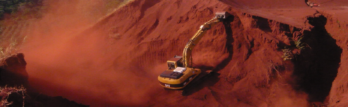
Site clearing is best carried out with a tracked bulldozer. Both vegetation and topsoil should be removed from within the footprint of the dam embankment. This can be done with a grader as well.
12.9.2 Core Trench Excavation
Core trench excavation can be done fairly efficiently with a bulldozer. For long core trenches, an excavator may be required to remove material from within the trench.
12.9.3 Borrow Excavation
Borrow excavation can be done with a wide variety of equipment. Excavators can excavate and load tippers very efficiently. Alternatively a bulldozer can rip and stockpile borrow and then a wheeled or tracked shovel can be used to load tippers. Dam scoops can also be used effectively.
Water can be added to borrow material at the borrow area or after placement on the working face. Typically a bowser and some hosepipes are required.
12.9.4 Placement
In general, material is placed on the working face using tippers and then spread with a grader, bulldozer or tracked shovel.
In some cases, material can be pushed from the borrow area on to the working surface with a bulldozer. This is most common in pans where the pushing distance is less than 60m.
Smaller construction site dumpers or tractors with tipping trailers can also be used.
Once spread, water can be added as needed to get the proper moisture content. It may be necessary to mix in the water with a harrow or similar machine in order to ensure uniform water distribution.
Compaction testing results also give water content information and after a few days of work and experience there should be good consistency in water application and water content.
12.9.5 Compaction
For compacting the type of soils used for embankment fills, the use of a sheepfoot roller is recommended. With this type of roller (either towed or self-propelled) the action of the feet causes significant mixing of the soil, thus improving its homogeneity, and will break up lumps of stiff material. Due to the penetration of the feet, excellent bonding is obtained between successive soil layers, which is an important requirement for water-retaining earthwork. Sheepfoot rollers are most suitable for compacting soils at water contents slightly lower than the optimum soil moisture content.
Many self-propelled, vibrating sheepfoot rollers are available in Kenya. Towed rollers can be used but may require either more passes or thinner layers to get proper compaction. When possible vibrating rollers are preferred.
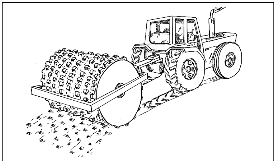
Figure 12-11: A Tractor Drawn Sheepsfoot Roller
Flat rollers can be used but they require scarification of the working surface to ensure bonding between layers.
12.9.6 Slope Trimming
Slope trimming can be done with graders or with bulldozers. Excavators can also be used for trimming slopes.
12.9.7 Concrete Works
In general, concrete works will require a mixer and poker vibrator. Hand mixed concrete and non-vibrated concrete should be discouraged.
12.10 Construction Supervision
The level of construction supervision required is dependent on a variety of factors including the size of the reservoir, the risk to downstream users, the competence of the contractor, and the payment structure adopted.
In general construction supervision will ensure a better finished reservoir.
The main construction supervision tasks can be broken down as:
- Site layouts;
- Confirming quality of materials and workmanship;
- Compaction testing;
- Pressure testing pipes;
- Compaction testing;
- Adapting design based on unforeseen site conditions;
- Recording design changes;
- Calculating quantities;
- Preparing payment certificates;
- Reporting to WRMA and the client as needed.
12.10.1 Site Layouts
Site layout is perhaps the most important part of a water storage project. It must be done with sufficient accuracy to ensure that the reservoir positioning is appropriate to the actual site. In the case of earth dams, the site layouts activity will continue throughout the embankment construction and will ensure that embankment slopes are built as per the design.
12.10.2 Compaction Testing
Compaction testing should be carried out throughout the construction of earth dams. Several samples should be taken for each layer. Conventional sampling and drying in an oven takes 24 hours, so there needs to be planning with regards to working areas and sample taking in order to ensure that layers and areas with insufficient compaction are not covered over before test results are ready.
Compaction testing requires a set of moulds, a drying oven, a scale (capable of reading to 0.1gm) and several graduated cylinders.
The actual calculations are easily done in a spreadsheet and results can be filed both hardcopy and electronically in case they are needed at a later date.
12.10.3 Pressure Testing Pipes
Pressure testing of pipes MUST be carried out before pipes are encased in concrete or buried. Pressure testing details are given in the sample specifications.
12.10.4 Recording Design Changes
Most projects will have some design changes in order to accommodate site conditions. These should be handled by the project engineer to ensure that they do not compromise the original design of the dam.
12.10.5 Adapting Design Based on Unforeseen Circumstances
In some cases, significant design changes will be needed due to unforeseen circumstances and it will be necessary to actually redesign portions of the project. This re-design work should be carried out by the project engineer.
12.10.6 Calculating Quantities
A large part of the construction supervision process involves calculating and recording quantities of materials and work. This is necessary to calculate payments due to the contractor, to minimize the chance of disputes and to ensure that the design figures are accurate.
12.10.7 Preparing Payment Certificates
Most water storage construction projects span several months and payments are usually based on actual work completed. Payment certificates must be prepared to detail amounts due to the contractor and to provide accurate records in case of disputes.
12.10.8 Environmental Protection
The main environmental issues during construction are generally dust, noise and pollution from oil or fuel spills. These can be dealt with on a case by case basis. In addition, worker safety due to site traffic should be given proper consideration and traffic flow should be controlled to minimise the likelihood of accidents.
Where there is water flow through the site and downstream water users, care must be taken to ensure that the water quality of the flow is not affected by the construction activities. This typically involves diverting flow around the site and may require pipes or culverts at road/equipment crossings.
12.10.9 Defects Liability Period
For contractual projects, the defects liability period is a duration specified in the contract, usually six months after practical completion, when the contractor is required to make good defects that may arise. A certain percentage of the contractor’s final pay is also retained during this period, such that in the event that the contractor does not honour this requirement, then the project owner may use this amount to rectify any defects that have occurred.
12.11 Operation and Maintenance
Operation and maintenance covers the range of tasks, some of which are routine, that enable the dam to provide the expected benefits over the life span of the dam.
Maintenance of small dams and reservoirs is simple and inexpensive but is nevertheless essential since unattended minor issues (especially minor erosion on embankment and spillway) can develop into major problems which can ultimately reduce the useful lifespan of structure.
12.11.1 Community Issues
For community owned dams, the following operation and maintenance issues should be considered. The community which will receive water from the dam has a major role to play in the operation and maintenance of the structure. During the construction (or rehabilitation) of the project the future dam operator and at least one other member of the dam committee should receive basic training in operation and maintenance aspects of the small dams. This training should concentrate on the following issues:
- Attending to minor problems which can be taken care of by the community itself, e.g. rain erosion on embankment slopes, repair of fences etc.
- Identification of problems which require more specialized attention, e.g. erosion in spillway channel.
- Establishment of communication channels between the representatives of the community (dam committee) and the responsible organisation or administration at County level.
Once the ownership of the dam has been formally transferred to the community, it will then be the responsibility of the dam committee to carry out regular inspections and basic repairs and maintenance works. A handing-over report including specific information and instructions on existing problems for the concerned dam shall be elaborated. Information regarding problems which require more specialized attention will be passed on to the relevant authorities without delay.
12.11.2 Embankment
Erosion due to rain or surface run-off on the embankment (downstream slope) must be controlled. Erosion rills on the embankment slopes should be re-filled with compacted material and grassed.
Any population of rats or other rodents should be removed, as they constitute a serious risk for the water-tightness and the stability of the dam.
Fences should be kept in good condition and repairs carried out when required. No livestock should be allowed to wander on the embankment.
Surface cracks should be noted and filled in as soon as possible. Longitudinal cracks along the crest indicate significant soil movement which could occur from settlement or as an early sign of slumping along the downstream or upstream slopes. Filling cracks with compacted material is an effective way to prevent them being filled with water which will further weaken the structure.
Erosion from wave action should be dealt with either through placement of additional riprap or by planting grass or reeds in the affected area.
Trees should be removed from the embankment before they can become established. Small brush and grass is the preferred embankment cover.
Any settlement along the crest should be filled in and the crest level should be kept at its design level.
Slumping on the embankment faces can be addressed by adding material to the base of the embankment to form a berm and reducing the length of the embankment slopes.
Seepage at the embankment toes should be noted and any standing water should be given a drainage pathway. The downstream area of the dam should not be allowed to become saturated.
12.11.3 Spillway
Spillway erosion requires lining with rip-rap or construction of gabions to stabilise the channel banks. If there is significant spillway erosion concrete sills may need to be installed to control spillway levels.
The spillway channel should be kept clear of high vegetation as this impedes the discharge capacity. Clearing of the channel should be carried out before every wet season. A short grass cover in the spillway should be encouraged as this provides an excellent erosion protection.
If possible records should be kept of spillway flows. This will help provide information for any rehabilitation work on the dam.
12.11.4 Reservoir Area
Removal of silt from the reservoir using manual labour can be periodically organised during the dry season. This will prolong the useful life period of the dam.
Water level readings should be noted as should any periods when the reservoir area is empty.
12.11.5 Water Quality
Water quality within the reservoir should be noted. For newly constructed dams there are often algal blooms after the initial filling of the reservoir due to the high level of organic nutrients. Algae growth can generally be controlled by introducing fish to the reservoir and examining carefully potential sources of nutrients to the water.
Turbid water within the reservoir can be a sign of catchment degradation and action should be taken to ensure that good catchment conditions are maintained.
12.11.6 Ancillary Structures
Outlet works should be checked and the main draw-off pipe should be flushed (in order to remove possible sediments) as needed.
Blocked outlet works can be cleared using compressed air or by back-flushing clean water up the outlet pipe. Care should be taken when doing this.
Valves should be operated during inspections to ensure that they are working properly.
Cattle troughs, tap-stands and water kiosks should be inspected and maintained. Drainage around these structures should be maintained to ensure no standing water is present.
Fencing should be repaired as needed and additional live fencing should be planted at the onset of rainy seasons.
12.11.7 Safety Issues
Observation of excessive seepage, wet patches or small slides on downstream slope, turbidity of seepage water etc. should be carried out. If seepage is observed, plans should be made to monitor the flow rate and determine if the seepage is increasing or is fairly constant and whether the discharge is correlated to the water level. Drainage channels should be installed to direct seepage away from the embankment and into the river course.
Turbid seepage indicates that the seepage is eroding its flow pathways and is a serious issue. It must be dealt with. It is best dealt with by excavating where the seepage is emerging and then backfilling with a sand/ballast/hardcore layered filter arrangement. The filter should retain any soil particles that are being carried by the seepage.
If there are concerns about the dam safety, water levels should be lowered as quickly as possible.
Fencing should be maintained to prevent uncontrolled access.
Floats or life preservers should be available and well maintained for dams in areas with human traffic.
Warning signs should be repainted as needed and placed prominently to warn people of the risks posed by the reservoir.
Contact lists of important government, riparian landowners and civil societies should be maintained and updated yearly. If there are concerns about the dam safety, the contact lists should be used to inform everyone of the situation.
If possible, inspections of the dam and reservoir should be carried out monthly, while special attention is required during the rainy seasons.
12.11.8 Inspection Schedule
Regular inspection of the structure is required to ensure problems are identified early and remedial action taken. The WRM Rule 2007 (Fourth Schedule) imposes the frequency and expertise required for inspections of dams according to the class of dam as shown in Table 12-9.
Table 12-9: Frequency and Expertise Required for Dam Inspections
| Class of Dam | Frequency of inspection | Inspection by |
|---|---|---|
| A (Low Risk) | Once in 5 years | Panel I C1, Panel I C2, Panel II C |
| B (Medium Risk) | Once in 3 years | Panel I C2, Panel I C1 |
| C (High Risk) | Once every 2 years | Panel I C2 |
Table 12-10 provides a simple form to support dam inspections.
Table 12-10: Sample Inspection Form
| DAM NAME: | DATE | ||
| MONITORED BY: | WATER LEVEL: | ||
| ITEM | CONDITION | ACTION REQUIRED | BY WHOM |
| CATCHMENT AREA | |||
| Erosion | |||
| EMBANKMENT (cracks, vegetation, erosion, slumps, leaks, animals) | |||
| Crest | |||
| Downstream slope | |||
| Upstream slope | |||
| Lining Material | |||
| SPILLWAY (debris, vegetation, erosion) | |||
| Sill Area | |||
| Culverts under Road | |||
| Channel | |||
| River confluence | |||
| DRAW-OFF WORKS | |||
| Status of Pump and Meter | |||
| WATER QUALITY | |||
| Colour/turbidity | |||
| Smell | |||
| Chemical Analysis required? | |||
| ENVIRONMENT | |||
| Details of Any Animals | |||
| Details of Any Plants | |||
| Accessibility to dam | |||
| SIGNED BY | |||
12.12 Rehabilitation of Small Earth Dams
If properly designed, constructed and maintained, the type of small earth dams under consideration, should reach a useful lifetime of 20 to 25 years before the need for significant rehabilitation work occurs.
12.12.1 Selection of Dams for Rehabilitation
The aim of rehabilitation works carried out on small earth dams should not only be to restore the dam and reservoir into their original condition, but also to upgrade the structure where possible so as to bring it in line with the design guidelines set out herein.
It is important to select structures for rehabilitation where the costs involved will yield the maximum benefits, and where a reasonable chance exists that climatological, agro-ecological and community involvement factors are such that after rehabilitation, the dam will have a useful lifetime in line with set expectations.
On the technical/economical side it should always be kept in mind that physical removal of sediment deposits using ordinary earth-moving methods is rarely feasible. It is nearly always more interesting to either raise an existing embankment where the topography allows, or otherwise construct a new dam downstream of the old silted reservoir, whereby the old reservoir will further act as a silt-trap. Removal of sediments by scooping provides a ratio (water storage volume / earth fill volume) of 1, where even a dam-site rated as poor will have a ratio of 3. Physical removal of silt does make sense on sites where the sediments removed can be used to widen and raise the embankment crest and where significant ancillary structures have been built around the existing dam.
Another important factor which needs to be assessed before rehabilitation works are decided upon is the agro-ecological situation, the erosion and the expected sediment yield of the catchment area.
Finally the potential for successfully involving the beneficiaries not only in a number of construction activities but particularly in operation and maintenance of the structure and their willingness to make long term investments in catchment improvement and protection works, is another factor which needs to be taken seriously into consideration.
12.12.2 Cause of Failure
Prior to any site rehabilitation, a careful analysis should be made to establish the cause of the failure or condition that has necessitated the rehabilitation. This may require a number of steps including:
- Interrogating any locals or witnesses to the event that caused damage;
- Obtaining original design or as-built drawings and reports;
- Obtaining photographs of the as-constructed structure;
- Obtaining rainfall and streamflow records for the event that caused damage;
- Conducting topographical surveys to ascertain high water marks with respect to spillway and crest levels. This can help to ascertain whether overtopping of the embankment occurred;
- Conducting topographical surveys to establish whether excessive embankment settlement took place. Observations of longitudinal cracks on the embankment could also signify slumping and slope failure;
- Soil sampling and analysis to establish embankment material which may be different to surrounding soils and may be different across the cross section of the embankment.
The cause of failure analysis is important to avoid investing in the rehabilitation of a structure that has a fundamental weakness that is difficult or expensive to overcome (e.g. no impervious core resulting in excessive seepage, embankment built out of dispersive soils). In addition, if the failure is caused by insufficient attention to operation and maintenance tasks, then a substantive review of the O & M schedule and those responsible should be undertaken. In many instances, the cause of failure is not immediately obvious and may be attributed to a number of different factors taking place in combination.
Once there is sufficient confidence that the cause of the failure or damage has been established, then efforts to design the rehabilitation works can commence.
12.13 Rehabilitation Works
The rehabilitation works must address the cause of failure as well as returning the structure to operational status.
12.13.1 Embankment Repairs
Figure 12-12 shows how an old embankment can be raised. All trees and vegetation are removed from the old (possibly eroded) embankment, after which the embankment is trimmed down (min. 0.30 m). Any loose material should be removed or stockpiled for reuse. The trimmed old embankment is used as an upstream core for the construction of the new embankment. Suitable soil has to be used for the fill, and the usual compaction procedures should be followed. It is recommended that a core-trench should be incorporated in the new embankment. Care should be taken to ensure a good contact between the old and new sections of the embankment, and between the foundation and new material.
At the same time, various other works to improve the embankment can be carried out if required, such as:
- rip-rap protection on upstream slope;
- incorporation of a filter blanket and toe drain etc.
Raising of an embankment will normally require the filling of the old spillway channel and the construction of a new spillway. Alternatively, the concrete spillway sill can be raised and erosion protection provided downstream of the sill.
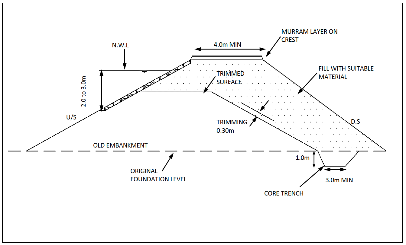
Figure 12-12: Raising of Embankment
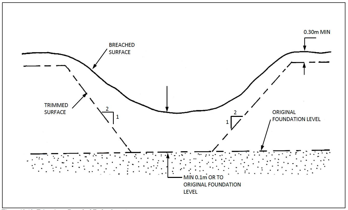
Figure 12-13: Trimming a Breached Embankment
Figure 12-13 and Figure 12-14 explain how a breached embankment is repaired. The breach is trimmed to a 2 to 1slope on the sides, the bottom is trimmed to the level of the original foundation (or at least one metre deep). All gully deposits (sand, gravel etc.) should be carefully removed from the bottom of the breach. Filling of the breach should be carried out using suitable soil and following the usual construction procedures for earthfill embankments.
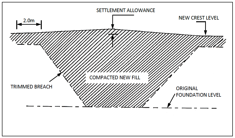
Figure 12-14: Repair of a Breached Embankment
12.13.2 De-silting
Prior to de-silting any reservoir by mechanical means, it must be emptied. This can be done by either pumping or cutting part of the spillway channel to the required depth. Breaching of the embankment is not recommended. The digging of a number of test pits in the reservoir, in order to establish the depth of the silt layer, prior to the scooping is recommended. This will also permit study of the stratification of the silt layer, which might eventually lead to determining its origin within the catchment.
If de-silting is carried out by traditional earth-moving methods, the most effective way would be to make use of a bulldozer (100-125 kW will generally be suitable) for the removing the silt, a wheel loader for loading it and tipping lorries for the transport of the silt. This basic machinery can be assisted by a number of smaller machines to perform more specific tasks.
If the removed soil is judged suitable, it can be re-used for repairing the embankment. In case of very small dams (below 5 metres of height), not involving drainage blankets or toe drains, removed soil, judged unsuitable for re-use as backfill can be used to reduce the downstream slope (see Figure 12-15).
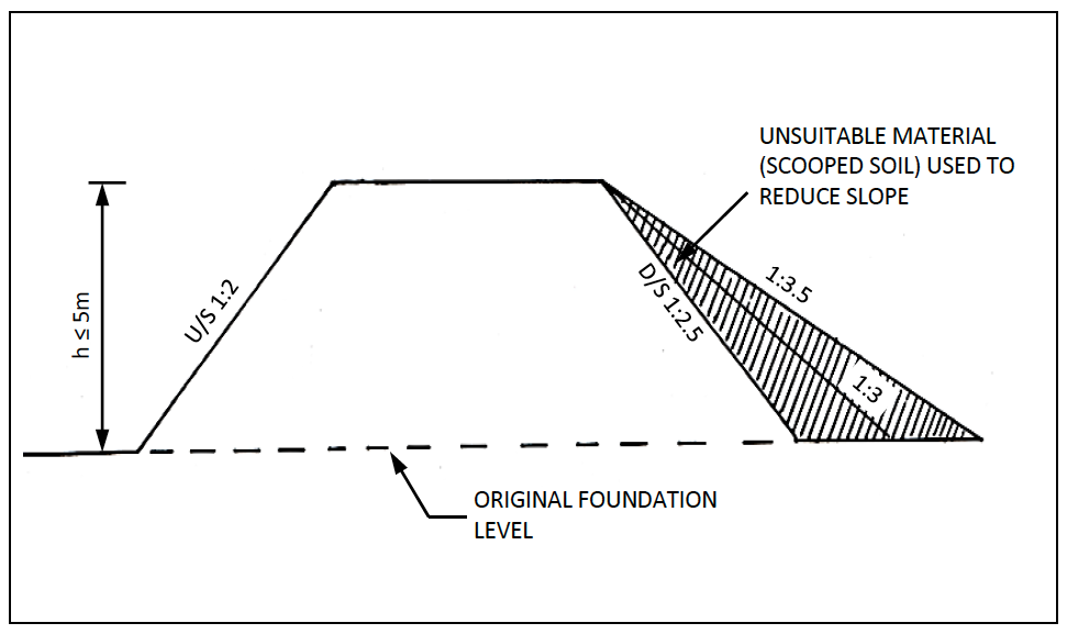
Figure 12-15: Use of Scooped Soil to Reduce Downstream Slope
12.13.3 Spillway Repairs
Repairs of old (eroded) spillways will usually involve the construction (or rehabilitation) of sills, lining eroded stretches with rip-rap (at least 0.30 m thick and compacted by a dozer), and stabilisation of banks by the use of gabions.
Whenever spillway repairs are undertaken it is suggested that the original spillway design calculations be confirmed and revised if needed due to changing catchment conditions or improved data on streamflow or rainfall.
13 Design of Mass Gravity Dams
Mass gravity dams are usually concrete or masonry walls constructed across water courses. They rely on the mass of the structure to provide stability against sliding and overturning. Although they can be designed and built for heights of up to 15m (or more), the taller structures become expensive in terms of materials and often alternative structures (concrete arch dams, buttressed walls, earth embankments, etc…) can offer more economical alternatives. In Kenya, mass gravity dams are most often built in the 3 to 5m height range and are most often used as controlling/offtake structures in river courses. When placed in a river channel to assist with water offtake or flow measurements mass gravity dams in Kenya are often referred to as weirs.
In keeping with low and medium risk structures, this manual only deals with mass gravity dams up to 5m tall. Mass gravity dams can be built much taller than this. For projects that exceed the 5m height limit, the following references can be consulted. Design of Small Dams, (United States Department of the Interior - Bureau of Reclamation, 1987) Hydraulic Structures (Novak, P., et al, 2006) or The Indian Standard, Criteria for the Design of Solid Gravity Dams IS6512-1998 (Civil Engineering Division Council, 1998).
Mass gravity dams can also be found in composite structures (part earth embankment, part mass gravity dam). Composite structures are not considered in this manual.
Curved or buttressed dams are not mass gravity dams as they use the curvature and/or buttresses to provide structural support to the dam. Curved or buttressed dams are not considered in this manual.
13.1 Typical Mass Gravity Dam Projects
Mass gravity dams are most suitable in areas where there are firm bedrock foundations and where the valley sides are also of a rocky nature. They are most often used as:
- Structures in river channels to raise water levels for water offtakes or diversions;
- Structures in river channels to assist in flow measurements;
- Small scale storage of water in arid rocky valleys;
- Storage and diversion structures in rock catchments;
- Storage structures for sand dams or other groundwater/subsurface dams.
Their main advantage over earth embankment dams is that the entire crest of the structure can serve as a spillway and that they are therefore less susceptible to erosion damage when overtopping. Other advantages include simpler and less costly offtakes as the offtake passes through a relatively thin wall compared to earth embankments.
Their main disadvantages over earth embankments are their foundation requirements (firm, stable rock foundations) and their costs. Costs for gravity dams can be quite high as transporting materials to site (sand, aggregate, cement, formwork, etc.) can be a significant expense.
13.2 General Considerations
The following factors should be considered when choosing a mass gravity dam.
13.2.1 Foundation
Foundations should be on bedrock in order to avoid seepage under the dam and for stability reasons. In case the rock formation is weathered, this profile should be completely excavated before the dam foundation is constructed. The presence of open fracture zones should also be investigated. If the presence of fracture zones is suspected, the rock surface should be cleaned and simple infiltration tests carried out by pouring water on the cleaned surface. If fractures are discovered, they need to be sealed, and expensive grouting might be required.
Mass gravity walls should not be built on softer foundations, but if there is no alternative (say for a proposed river offtake), then the wall should be keyed into the river bed (if possible a distance of ½ the height of the wall would be appropriate) and upstream and downstream aprons should be constructed. The wall will almost certainly have to be extended into the river banks as well. Typically a 5m extension into each bank should be sufficient to avoid erosion issues on the river banks.
13.2.2 Dimensions
Length of Wall: In general, walls longer than 30 to 35m should be avoided. Longer walls may require buttresses or other supports.
Height of Wall: In general wall height should not exceed 5m. Wall height will be limited to the depth of the river channel and must leave an allowance for flood flows such that the expected flood flows will still remain within the channel.
Wall Geometry: In general, crest widths range from 0.3m to 0.5m depending on construction materials and height of wall. Base widths range from 0.6 to 1.0 times the height (h) depending on construction materials and design of the wall. The front face of the wall can be vertical or with a slight slope toward the crest. The rear face generally has a slope of 1 horizontal to 2 vertical or similar.
13.2.3 Overflow Sections
The design flood and the broad crested weir formula can be used to calculate flow depths and approach heights for mass gravity dams. Depending on bank conditions, it may be necessary to leave an overflow section in the wall to keep flow away from erodible areas. This can be done by building wall sections slightly lower (0.30- 0.40 m) as shown in Figure 13-1.
Figure 13-1: Overflow Sections for Gravity Walls
For walls situated on firm foundations and with rocky banks, the entire crest can be allowed to act as an overflow. If this is the case, the rear crest edge should be rounded and the downstream face should have a gentle slope. The transition area between the downstream face and the riverbed should be gently rounded and the river bed must be firm rock that will not erode.
13.2.4 Upstream and Downstream Aprons
Depending on foundation conditions, it may be necessary to construct both upstream and downstream aprons.
Upstream aprons are usually required where the foundation rock is weathered or where the mass gravity wall is being built on softer materials. A 300mm thick reinforced concrete apron extending 1 to 2 meters upstream and covering the entire width of the riverbed will normally be sufficient. The apron should be cast on the foundation material without any hardcore underneath it. Placing material under the apron will lead to seepage problems.
Downstream aprons are required where there are concerns about erosion at the downstream toe of the mass gravity wall. They must be positioned and sized appropriately to avoid erosion at the downstream toe of the mass gravity wall. As with the upstream aprons a 300mm thick reinforced concrete apron extending across the entire river bed is recommended. The length of the downstream apron (where length is the distance the apron extends downstream from the toe) depends on the height of the wall. As a quick rule of thumb, the apron should extend a distance equal to the height of the wall.
Downstream apron positioning and design is highly dependent on foundation conditions. In easily erodible channels, it might be necessary to construct a stilling basin rather than a simple apron. It may also be necessary to consider other forms of energy dissipation in order to reduce water velocities. This can be done with rocks or boulders set in the apron.
13.2.5 Wing Walls
Wing walls are walls constructed both upstream and downstream of the mass gravity wall. They are positioned parallel to the river/valley banks and serve to protect the banks from erosion. They are effectively retaining walls and should be designed as such. They must extend above the sill level of the mass gravity wall in order to fully protect the banks during high floods. They normally do not extend more than 5m upstream and 3m downstream from the mass gravity wall.
Wing walls can often be used for positioning offtakes. As they are out of the main river channel they are better protected from flood water damage and can be less susceptible to siltation.
13.2.6 Draw-Off System
Draw-off systems for gravity dams can be similar to those for small earth dams as shown. A simple through-the-wall draw-off arrangement is shown in Figure 13-4.
A through-the- wall system will involve a perforated or slotted GI pipe (usually laid horizontally) surrounded by a hardcore/ballast/sand filter, a draw-off pipe through the gravity wall (diameter preferably 75 mm or larger), and a small valve chamber. To minimise the risk of seepage along the pipe two or more (welded) steel collars can be provided where the pipe traverses the wall. Additionally, several scrap iron lugs should be welded to the pipe where it passes through the wall to ensure that the pipe will not spin in the wall when fittings are screwed on or off. To save money, a reducer and smaller gate valve can be used with appropriate fittings.
Alternatively, in situations where the dam is used to control flows, an overflow section that spills into a collection chamber can be placed in the wall. All pipe connections can then be made from the collection chamber. Appropriate screens and washouts should be included in the collection chamber design. This overflow and collection arrangement is called a side chamber offtake in Kenya and is very useful for ensuring an agreed upon distribution of flows. Where the dam is used to control flows for common intakes and self-regulating intakes, multiple overflow sections and collection chambers can be installed.
The final position of collection chambers is highly dependent on site topography and final pipeline routes. They are generally positioned to reduce the risks of erosion, to minimize construction costs and to reduce pipeline river crossings.
13.2.7 Scouring System/Compensation Flow
For gravity walls used as weirs in river courses, it is often desirable to install a scouring system or to ensure compensation flow.
Compensation flow can be addressed with a pipe through the wall as described above. Pipe size can be roughly calculated based on pipe cross section area and an assumed velocity of 1m/s. Compensation flow pipes can often be blocked and can become contentious issues during low flow periods. If there is concern about compensation flow during low flow periods, then it is safest to us an overflow offtake with a downstream collection chamber and install an overflow section for the compensation flow that ensures the priority of the compensation flow.
Scouring pipes through the wall must be extremely large diameters to work effectively. They are most often used as part of the diversion works during construction. Pipes with flanged fittings on the downstream side are most appropriate. The flange can be sealed with a blank plate during normal use. The plate can be loosened and then pivoted about one securing bolts during scouring operations. This removes the need for a large diameter gate valve on the scour pipe.
Even with a large diameter scour pipe, it will be necessary to manually assist in silt removal. Deep deposits must often be pushed into the area where they can be flushed through the scour pipe.
13.3 Specific Calculations
In addition to the previously discussed calculations on hydrology, storage and evaporation, water use, etc., the following standard calculations are useful in the proper design of gravity dams:
- Storage capacity;
- Check for overturning;
- Check for sliding;
- Broad crested weir flows;
- Inlet screen flows.
Larger mass gravity wall designs (over 5m tall) should also consider:
- Foundation stresses;
- Uplift pressures;
- Earthquake forces;
- Wind and wave pressures;
- Tension forces under various loads.
13.3.1 Storage Capacity of the Reservoir
The (total) storage volume of the reservoir can be estimated from the geometry of the riverbed (see Figure 13-2) using Equation 13-1.
Figure 13-2 Geometry of River Bed for Storage Volume Calculations
Equation 13-1
$\mathbf{V = \frac{1}{2}(H \times L \times W)}$
Where:
V = Storage Volume [$m^3$];
H = height of wall [m];
L = horizontal distance water will occupy in meters and can be calculated as
L = [h x 100] / [slope of riverbed (%)].
13.3.2 Design of the Gravity Wall
Gravity walls can be built from anything that provides sufficient mass. In Kenya they are generally built from concrete (1:2:4 mix, not reinforced) or from stone masonry using blocks obtained from natural rock (hard rock is preferable) or from rubble stone masonry with waterproof mortar.
For design purposes, the density of concrete can be taken as 2,400 kg/m3 and the density of masonry can be taken as 2,300 kg/m3 (IS 6512-1984). Actual measured densities for proposed materials can be used for final designs.
Mass concrete is defined by the American Concrete Institute as:
Any volume of concrete with dimensions large enough to require that measures be taken to cope with generation of heat from hydration of the cement and attendant volume change to minimize cracking.
For mass gravity walls under 5m tall, it is unlikely that hydration heats will cause temperature problems in the concrete. However, if the minimum dimension of a concrete pour for a gravity dam is greater than 1m, then additional advice on mass concrete works and temperature control should be taken. BS8110 is an excellent reference for mass concrete.
The foundation of the wall should be on rock and the foundation area should be either horizontal or slightly sloping towards the reservoir. It is preferable to anchor the wall at least 0.50 meters into the foundation (see Figure 13-3). In order to ensure the water-tightness of the reservoir, special attention should be paid to the contact zone between the rock and the wall. When a masonry wall is used, it should be plastered (20--30mm) with cement mortar on the reservoir side or alternatively waterproof mortar can be used in the masonry wall (a 1 to 3 cement/sand mix with 1kg waterproofing cement to 50kg regular cement is a general ratio for waterproof mortar mixes).
Figure 13-3: Stability Computations for Gravity Walls
The wall should be dimensioned to resist water pressure. Stability against sliding and over turning should be verified. The following formulae are applicable (see Figure 13-3):
Equation 13-2:
$\mathbf{F_h = P = \frac{w \cdot H^2}{2}}$
Where:
$F_h$ is the horizontal force on the wall in kN per m of width;
P is the pressure in kN per m of width;
W is the unit weight of water = 9.81 kN/$m^3$;
H is the height/depth of water in m
The overturning moment can be calculated as:
Equation 13-3:
$\mathbf{M_o = \frac{P \times H}{3}}$
Where:
$M_o$ is the Overturning Moment in kN m per m of width;
P equals $F_h$ the horizontal force on the wall in kN per m of width;
H is the height/depth of water in m
Equation 13-4:
$\mathbf{M_r = \frac{b' \cdot F_v}{2}}$
Where:
$M_r$ is the Resisting Moment in kN m per m of width;
b' is the moment arm in m (calculated depending on wall geometry and should align with the centre of mass of the structure);
$F_v$ is the weight of the wall in kN per m of width.
(Suggested density values for typical construction materials are 22-24kN/$m^3$ for mass concrete, 23-25kN/$m^3$ for reinforced concrete and 24-27kN/$m^3$ for stone masonry using natural rocks)
Safety factors are calculated as:
Equation 13-5:
$\mathbf{F_s = \frac{r \cdot F_v}{F_h}}$
Where:
$F_s$ is the Factor of Safety for Sliding;
r is the static fricition coefficient (suggested 0.55 for foundation on solid rock, 0.45 for foundation on material with coarse granulometry which does not contain silt or clay and 0.35 for all other cases);
$F_v$ is the weight of the wall in kN per m of width.
$F_h$ is the horizontal force on the wall in kN per m of width.
Equation 13-6:
$\mathbf{F_{o.s} = \frac{M_o}{M_r}}$
Where:
$F_{o.s}$ is the Factor of Safety for Overturning;
$M_o$ is the Overturning Moment in kN m per m of width;
$M_r$ is the Resisting Moment in kN m per m of width.
Safety factors with respect to sliding ($F_s$) and overturning ($F_{o.s}$) should not be less than1.5.
In general, the top width of the wall (a) should not be less than 0.30 m. For walls higher than 2.50m, the top width should preferably not be taken less than 0.50 m.
13.3.3 Overflow considerations
The most important overflow calculation is to use a suitable design flood to confirm the approach height that will result when the weir is passing the design flood and then to ensure that the approach height will not result in any “out of bank” flows in the stream bed around and upstream of the weir. The broad crested weir formula can be approximated as follows in Equation 13-7. This equation can be rearranged to solve for the depth of flow or the discharge can be calculated for various flow depths until a flow depth that matches the design flood flow is determined.
Equation 13-7:
$\mathbf{Q = 1.78 \times L \times d^{\frac{3}{2}}}$
Where:
Q = discharge [$m^3$/s];
L = length of the overflow section [m];
d = depth of flow over the weir [m] measured far enough up-stream.
A factor of safety is prudent to ensure that the design flood Q can be passed within the overflow section. Equation 13-8 provides an estimate for the final depth of the overflow section.
Equation 13-8:
$\mathbf{D = 1.5d + 0.1}$
Where:
D = Final depth of overflow section [m]
Equation 13-7 can also be used to determine flow through various widths and depth of openings when the weir is used as a flow regulation device.
When the length of the weir is small compared to the flow depth, alternative equations may give more accurate flow measurements.
13.3.4 Uplift Pressures
In the event that the mass gravity dam is constructed on a semi-permeable surface, or where the foundation may have cracks, concerns may arise on the effect of uplift pressures on the structure. This can be resolved by incorporating a filter drain on the downstream section of the structure to dissipate such pressures. Reference should be made to detailed design documents if there is the possibility of uplift pressures.
13.3.5 Drawoff Pipe Sizing
Draw-off pipes in gravity dams are generally a fairly large diameter where they pass through the wall in order to ensure a good contact area between the pipe and the mass gravity wall. Three inch diameter, heavy gauge GI pipe is recommended for most applications. A quick flow check can be made using the proposed pipe cross section area and an assumed velocity of 1m/s. Inlet screens can be positioned as shown in Figure 13-4 .Inlet screen sizing can be carried out based on a required open area calculation. If velocities in the screen are restricted to 0.025m/s, then Equation 13-9 will give a figure for the required open area in the inlet screens. This can then be used along with perforation size and positions to determine a length of inlet screen required.
Equation 13-9:
$\mathbf{A = Q/V}$
Where:
A is the required open area in the inlet perforated pipe [$m^2$];
Q is the desired flow from the dam [$m^3$/s];
V is the velocity of the flow in the inlet screen and is set at 0.025 m/s.
13.4 ALDEV Weir Dimensions
The ALDEV weir design was developed by the Arid Land Development Programme in Kenya in the 1950s. It has proven to be a robust design suitable for mass gravity dams less than 5.0m in height and less than 50m in length. Figure 13-4 shows a typical cross section for the ALDEV Weir. The crest and base widths are calculated from the height of the wall. The crest width is 0.2xMax Height and the base width is 0.75xHeight.The upstream face slope is approximately a 7 degree slope toward the crest. A more detailed drawing is provided in Appendix B.
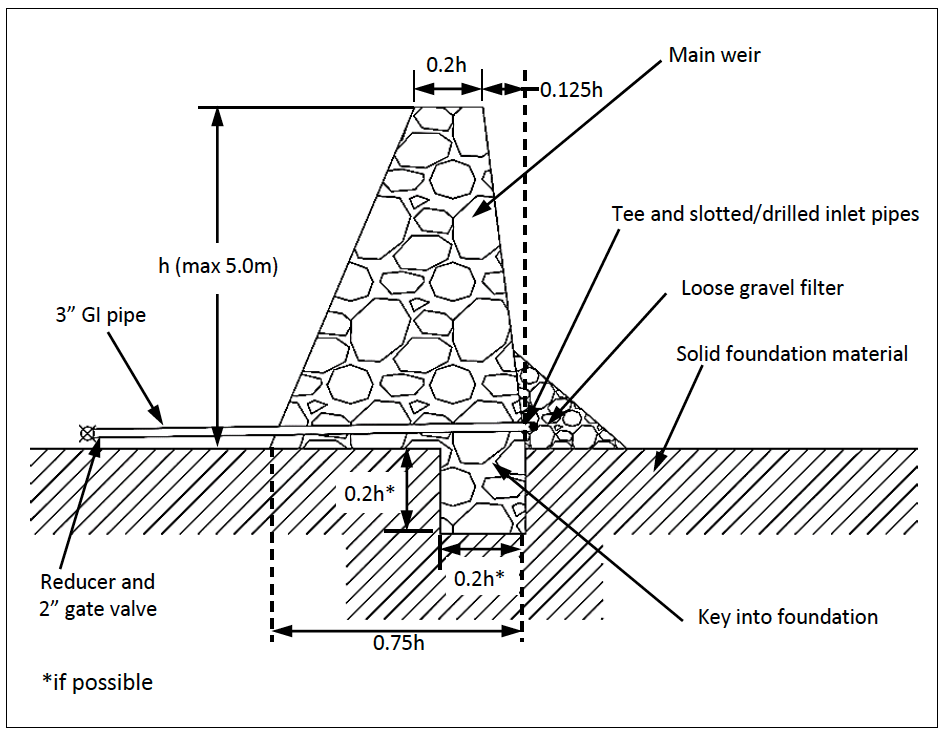 Figure 13-4: Typical Cross Section for ALDEV Weir
13.4.1 Typical ALDEV Wall Dimensions and Volumes
Table 13-1 shows typical values for varies wall heights. Material volumes can be calculated from cross sectional areas and the length of the wall. Typically a ratio of 75% stone to 25% mortar (of 1:3 cement:sand mix) is used. Mortar should incorporate waterproof cement (usually 1kg per 50kg cement).
Table 13-1: Typical Dimensions for Various Heights of Aldev Weir
| Height (m) |
Crest Width (m) |
Key Depth (m) |
Key Width (m) |
Base Width (m) |
Cross Section Area ($m^2$) |
|---|---|---|---|---|---|
| 0 | 0 | 0 | 0 | 0.6 | 0 |
| 0.5 | 0.1 | 0.1 | 0.1 | 0.6 | 0.2 |
| 1 | 0.2 | 0.2 | 0.2 | 0.8 | 0.5 |
| 1.5 | 0.3 | 0.3 | 0.3 | 1.1 | 1.2 |
| 2 | 0.4 | 0.4 | 0.4 | 1.5 | 2.1 |
| 2.5 | 0.5 | 0.5 | 0.5 | 1.9 | 3.2 |
| 3 | 0.6 | 0.6 | 0.6 | 2.3 | 4.6 |
| 3.5 | 0.7 | 0.7 | 0.7 | 2.6 | 6.3 |
| 4 | 0.8 | 0.8 | 0.8 | 3 | 8.2 |
| 4.5 | 0.9 | 0.9 | 0.9 | 3.4 | 10.4 |
| 5 | 1 | 1 | 1 | 3.8 | 12.9 |
Note:
- Achieving key depth and width can be very challenging.
- Use a fixed crest width based on maximum wall height.
13.5 Sample BoQ, Specifications and Reporting
A sample BoQ and Specifications for a rubble stone mass gravity dam are available on the website. A sample design report format is available in Chapter 19 of this document.
13.6 Construction Issues
Mass gravity dams should make as much use as possible of locally available materials. This often means constructing of local stone and mortar.
13.6.1 Foundation Preparations
Foundations must be cleaned of all loose material. In the event of weathered or cracked foundations, it may be necessary to grout or infill with a cement slurry. It may be necessary to use a wider base width to ensure a water tight seal along the foundation. Where possible a key trench should be excavated in the foundation material.
13.6.2 Materials Preparation
Sand, ballast, cement, steel (if required) and formwork should be stockpiled on site. Sufficient water must be available for the volume of concrete or mortar required. Water availability is often the largest constraint in constructing mass gravity structures in arid areas. Temporary water tanks and bowsers may be required during construction and during the curing period after construction.
13.6.3 Construction Schedule
For mass gravity dams less than 5m tall and less than 50m in length, construction can generally be carried out in 1 to 3 months with an approximate schedule given below.
| Site preparation | 2 weeks |
| Material Delivery | 2 weeks |
| Construction | 4 to 8 weeks |
| Curing | 3 to 4 weeks |
| Site Reinstatement | 1 week |
13.7 Equipment
For the size of mass gravity walls described in this document, the following specialized equipment will be needed.
- Cement mixer;
- Wheel barrows;
- Hosepipe level (or construction level);
- Poker vibrator (if mass concrete is to be used in the foundations or aprons).
Most foundation works can be undertaken with manual labour and normal hand tools (hoes, shovels, mattocks, crowbars, sledge hammers…..). Most masonry works can be undertaken with manual labour and normal masonry tools.
13.8 Construction Supervision
While a site engineer or clerk of works is generally sufficient to ensure reasonable quality control for most mass gravity dam projects, for larger structures, it may be beneficial to put in place strict quality control measures. These may include both cone tests during concrete pouring and cube tests to ensure proper concrete quality.
13.9 Operation and Maintenance
Operation and maintenance of mass gravity walls is fairly simple. The main concerns are erosion (either at the downstream toe or around the wall in the river banks) and siltation.
Erosion should be monitored and repairs carried out as needed during low flow periods. Repairs to the downstream apron will generally involve concrete works to fill in eroded areas. Repairs to the riverbanks/wing walls may involve gabions or additional masonry wall construction.
Siltation is best dealt with during normal flow periods. Silt can be removed through the use of washouts (if installed) or manually.
Where mass gravity walls are used as offtake structures, offtakes can be blocked with leaves and floating debris and should be regularly monitored and cleaned.
13.10 Rehabilitation
Rehabilitation of failed mass gravity dams depends on the original cause of failure. Erosion failures (either below the wall or around the wall) can be repaired with either mass concrete or gabions. Structural failures (either from poor original construction or from improper design) are more difficult to address and it may be better to construct an entirely new wall.
14 Design of Water Storage Pans and Lagoons
Water storage pans are excavated surface water storage facilities of limited capacity (generally not exceeding 20,000$m^3$) which are mainly constructed in locations where the topography does not allow the construction of a small dam and instead favours excavation. Excavation of larger pans (up to 150,000 $m^3$) is possible and can be done, especially near populated centres, but the construction cost is generally high due to the 1 to 1 excavation to storage ratio. Often natural depressions can be enlarged to produce pans with a slightly better storage to earthworks ratio.
Recently in Kenya, lined pans (or lagoons) with storage capacities of up to 70,000 cubic meters have become popular with horticultural farmers.
Pans are excavated below the natural ground level, and with the exception of pans constructed on inclined locations, the volume of earth excavated will be equal to the storage capacity of the pan. Compared to a small dam, the water to earth ratio (water storage volume / earth excavated volume) – (see Section 10.7) is unfavourable. However, when a suitable inclined location can be identified for the construction of the pan a somewhat more favourable ratio can be obtained. An example of a pan constructed on an inclined location is shown in Appendix B Type Drawing VIII - Water Pan on Inclined Location. Storage pans tend to be relatively expensive constructions when compared to small earth dams.
Water storage pans are subject to the same limitations regarding sedimentation and evaporation as small dams (see Section 3.3 and 8.13). Due to their shallow depths (usually 2.50 m to 5.00 m) water storage pans are usually not suitable as permanent water sources for high evaporation areas, while for catchment areas subject to erosion, silt traps will have to be included in the design.
14.1 Merits and Demerits of Pans and Lagoons
Despite their increased use for water storage, pans and lagoons have a number of advantages and disadvantages as outlined in Table 14-1:
Table 14-1: Some Merits and Demerits of Unlined Pans and Lagoons
| Unlined Pans | Lagoons | |
|---|---|---|
| Merits | Less complicated construction compared to dams | Can be constructed on any soil type |
| Structural failure not a concern | Lined so seepage is not a constraint | |
| Demerits | Elevation restricts conveyance by gravity | Expensive to construct |
| Unfavourable water to earth ratio | Small tear in lining can lead to failure | |
| High evaporation losses | ||
A typical pan design should include the following drawings:
- Site map (google, 1:50,000 or 1:100,000 contour map);
- Site layout (showing water flows);
- Inlet channel cross section and longitudinal profile;
- Outlet channel cross section and longitudinal profile;
- Cross section (pan and silt trap);
- Control/spillway/overflow sill details;
- Inlet/outlet details/ramp details.
The following sections look at unlined pans in arid areas and lined lagoons for commercial water storage.
14.1 Guidelines for the Design of UNLINED Water Storage Pans in ASAL Areas
Unlined pans in arid areas are generally less than 5 m depth and water is mainly used for livestock. Appendix B gives the following drawings for unlined storage pans:
- Type Drawing VI: 11,600 cubic meters;
- Type Drawing VII: 20,000 cubic meters;
- Type Drawing VIII: 17,000 cubic meters on inclined site.
Recent experience (2000 to 2014) has shown that unlined pans can generally be constructed for approximately 500 ksh per cubic meter of soil excavation.
14.2.1 Location
Pans for the purpose of surface water storage can be constructed wherever a sufficient quantity of water can be intercepted to create a small reservoir. Pans are basically used in such locations where no topographically suitable site can be found for the construction of a small dam, or where no suitable construction materials for the construction of a dam can be found.
Apart from the two factors mentioned above (topography and availability of construction materials), the same basic principles for selection of appropriate locations as explained in Chapter 10 will apply. Particular attention should be paid to:
- The water-tightness of the reservoir in sandy areas: Contrary to earth dams, lining of the reservoir with an impervious clay blanket can often present a solution for pans, since reservoir dimensions in this case are limited.
- The natural drainage and flow pattern of the intercepted water: Spillways are not generally provided for pans, but an overflow structure for any excess water towards the natural drainage is included in the design. The slopes of any overflow or diversion channel must be considered carefully to reduce erosion.
- Silt trap requirements. Silt traps are normally included in the construction of unlined pans. Often, the silt trap is combined with the overflow structure.
- Sedimentation, evaporation and ecological impact along the same lines as set out under Chapters 3, 6 and 8.
-
Pans are generally laid out in a rectangular arrangement and careful thought should be given to the specific alignment of the pan. Pans constructed on an inclined surface should be positioned to minimize earthworks. This usually means placing the long side of the rectangular pan parallel to the natural ground contours (See Figure 14-1 for a typical pan layout).
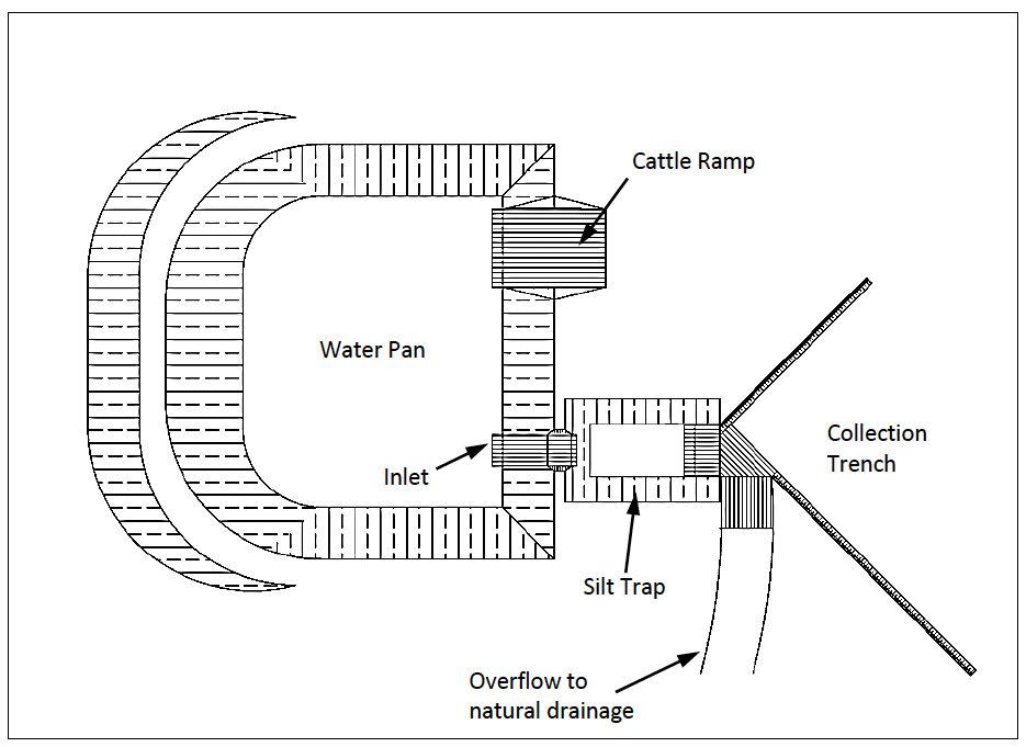
Figure 14-1: Typical Site Layout showing Silt Trap and Overflow
- Storage sizes should be considered carefully and need to address the expected inflows and the expected water use. Generally pans in arid areas should be sized with emphasis on availability of grazing (i.e. the pan should dry out just as the available grazing is finished). Large pans may result in overgrazing in the area around the pan.
14.2.2 General Consideration
The size of the pan will generally be a function of the required storage. The maximum capacity of a single unlined water storage pan in an arid area is generally 20,000$m^3$. If the required storage exceeds this capacity, more than one pan should be constructed. The exception to this rule is in built up areas where the pan will serve as a permanent water source. In such cases, larger pans can be justified. Pans of up to 150,000 $m^3$ of storage have been constructed in Kenya.
The depth of water storage pans will generally not exceed 5.00 metres, and will in no case be less than 2.50 metres. Which depth is adopted depends mainly on the type of soil in which the pan is excavated. Deep pans are possible in soils with a good granular distribution and impervious properties. In the case of sandy soils or heavy clay soils, the depth of excavation will be limited in order to assure the stability of the slopes of the reservoir walls and shallow pans will be preferred. From the point of view of evaporation, a deep pan is of course preferable to a shallow one.
The shape of the pan depends mainly on the available land. Generally, pans are rectangular or square. Round pans are possible but they can be quite difficult to lay out properly.
The slopes of the excavated pan (and silt trap) will generally be 1 (v) to 2.5 (h), except when relatively deep pans need to be constructed in sandy or heavy clay soils. In these cases, slopes of 1 (v) to 3(h) or shallower can be adopted.
The construction of water storage pans in relatively pervious soils is only possible if sufficient water-tightness of the reservoir can be achieved. In cases where the excavated reservoir is judged insufficiently impervious (sandy soils, fissured rock bottom etc.), lining of the reservoir with a 300 mm thick clay blanket can be a solution, if sufficient clay is available within the vicinity of the site.
14.2.3 Inlet and Overflow Structures
In order to convey water into the pan, two collection trenches (see Type Drawing VI- Water Storage Pan for details) are usually constructed. To avoid high flow velocities and erosion, the slope of those trenches should not exceed 1%. They can either be constructed with an angled dozer or grader blade. Length and exact location for each pan site has to be determined as a function of the topography of the site.
Whether the construction of a silt trap will be required or not, depends largely on the expected sediment yield from the catchment (see Section 8.13). Flat catchments with good vegetative cover produce less silt than steep or overgrazed catchments. Depending on the expected silt load, the dimensions of the silt trap will usually be either 15.00m x 25.00m or alternatively 20.00m x 30.00 m. Depth of silt traps will usually be 2.00 metres. The trap efficiency (see Figure 8-13) of the silt trap will gradually decrease as the silt trap fills up. Hence it is highly desirable to de-silt the silt trap at regular intervals.
Flow of water through the pan should be avoided in order to prevent large sediment deposits in the reservoir. As a general rule, once the maximum water level in the pan is reached, any excess water should be diverted away from the pan. Hence the inlet sill level should be determined accordingly.
Details of inlet and overflow sills are given in Appendix B Type Drawing VI-Water Storage Pan. Width of the inlet sections to silt-trap and pan should not be less than 6.00 m.
Inlet and overflow sections need to be protected against erosion by an adequate rip-rap protection of at least 300 mm thick. Impervious clay blankets need to be extended to these areas in cases where they are required (see Type Drawings VI , VII and VIII).
14.2.4 Outlet Structures
The choice of outlet structure depends mainly on the expected water users. If the pan is to be used solely for livestock, then a cattle ramp can be installed (see Type Drawing VII). This requires minimal maintenance and is the simplest “outlet structure” to construct and maintain.
If the pan is to be used for domestic water supply, the best option is generally a well dug beside the pan. The well can be equipped with a hand-pump or a bucket and windlass (see Type Drawing VI and VIII). Water flow into the well can be improved through the use of an infiltration gallery. Provision should be made for a cattle trough to be supplied with water from the well.
As small petrol pumps have become more common in Kenya, water use can be done through the use of a pump. In such cases, several level area where pumps can be positioned should be established during construction. Care must be taken to avoid polluting the water with spilled petrol or oil. Permanent pipe installations are not recommended as they are prone to damage and theft.
14.2.5 BoQs and Specifications
BoQs and Specifications for a selection of unlined pans are available on the website.
14.2.6 Construction Details
Type Drawing VI - Water Storage Pan - shows a typical rectangular pan, 4.00 metres deep, and with a total storage capacity of 11,600 $m^3$, equipped with a large (20.00m x 30.00m) 2.00 metres deep silt trap. Construction details of concrete sills and collection furrows are also given
Sills should be made of Class 25 (1:2:4 mix) mass concrete. They can either be 0.70 metres (preferably) or 0.50 metres deep.
This drawing also shows the usual way of disposing of the excavated material. Excavation of pans is started by “stripping" the proposed area of 0.20 m - 0.30 m of topsoil. This topsoil is then stockpiled for later use as a cover to the excavated material. The excavated soil is disposed of as shown in Type Drawing VI, in a berm, not higher than one metre, with slopes of 1 to 10, and covered with topsoil to induce vegetative growth. The width of the berm depends on the quantity of excavated soil available.
Properly compacted rip-rap protection (compaction by dozer) of not less than 300 mm thick should be used where indicated. Angular rip-rap (100 - 200 mm) from solid rock is preferable. For cattle ramps the rip-rap layer should be covered with gravel.
Type Drawing VII - Standard Water Pan 20,000 $m^3$ - shows the construction details for a more elaborate water storage pan, where the excavated soil has been utilised to construct a 3.00 metre high embankment around the whole pan. This type of embankment needs to be properly compacted. In this case, the storage pan can remain unfenced. This Type Drawing also illustrates the use of an impervious clay blanket lining.
Type Drawing VIII - Water Pan on Inclined Location/Dug Well and Filter - shows details of a 11,700 m3 capacity pan on an inclined location, where a berm made from compacted excavated material has been used on the lower side, as well as all relevant details of the well and filter for abstracting water for human consumption.
14.2.7 Equipment
Although small pans can be constructed with manual labour (usually up to about 10,000 cubic meters of storage and usually done under food for work or cash for work programmes) it is most common to use mechanized equipment.
A small pan can be constructed with the use of a bulldozer where the bulldozer simply excavates and pushes material. Push distances should be kept less than 60m.
Larger pans will also require a bulldozer as well as some sort of loader (wheeled or tracked) and several tippers. When push distances exceed 60m it is generally less expensive to load tippers and then haul and dump at the appropriate spoil area.
While larger excavators can be used to both excavate and load tippers, they do not produce uniform excavated slopes unless they have a skilled operator.
14.2.8 Construction Supervision
Construction supervision should be most intensive during the initial site layout. Once laid out weekly visits to ensure that the design is being followed should be sufficient.
Competent small contractors can usually shift 300 to 700 cubic meters of soil per day. Larger contractors may shift up to 1,000 cubic meters of soil per day. Using those figures, a 20,000 cubic meter pan could take 20 to 66 days to construct.
14.2.9 Operation and Maintenance of Unlined Pans
The main problems encountered with unlined pans are:
- Not filling;
- Excessive seepage;
- Excessive sedimentation;
- Controlling livestock access;
- Poor water quality;
- Difficulties in extraction of water.
In the event of a constructed pan not filling, efforts should be made to increase the catchment area for the pan. This can be done by constructing contour bunds to collect water from a larger area. Alternatively inlet structures and canals to capture flood flows from nearby rivers or laggas can be constructed.
For a pan that fills but then quickly loses water to seepage, lining should be considered. Typically a 200 to 300 mm thick clay lining will be required. Artificial linings will not withstand long empty periods and are easily damaged by livestock and wildlife. Bentonite or other commercially available clays can be added to the existing soil to reduce permeability. These can be purchased from local mining companies.
Excessive sedimentation can be addressed through improvements to silt traps, improved control of inflows or catchment improvement campaigns.
Livestock access can be controlled by fencing. If possible live fencing is recommended. Community awareness raising can also be undertaken to reduce uncontrolled livestock access.
Poor water quality can be address with an improved offtake. An offtake that incorporates a sand/ballast filter is recommended.
Difficulties in extracting water can be addressed through improved offtakes and or pumped offtakes. Most offtake improvements will significantly increase the operating costs of the reservoir.
14.2.10 Rehabilitation of Unlined Pans
Rehabilitation works will mainly concentrate on removal of silt (effectively re-excavating the pan) or improvements/repairs to the offtake works.
During rehabilitation it might also be necessary to extend or improve any inflow channels.
14.3 Guidelines for the Design of Lined Lagoons
Recent changes in the availability of HDPE and LDPE lining material have resulted in lagoons being adopted by commercial farmers. Commercial lagoons can be up to 70,000 cubic meters in storage and may have water depths of up to 7m.They are generally positioned to collect runoff from greenhouses or other farm structures. Such lagoons will have a lined spillway and it should be sized to meet the expected maximum runoff flow.
In the context of this manual, lagoons differ from pans in that they are always lined with an artificial lining material and they are normally constructed on sloping land. Construction on sloping land means that part of the lagoon will be an earth embankment dam and part of the lagoon will be an excavated pan.
A typical lagoon drawing with details on topography and associated structures is provided in Appendix B Type Drawing XII – Lined Lagoon on Inclined Location. It should be noted that the final design/layout of a proposed lagoon will depend on the topography of the land and the availability of space.
Lagoons can generally be constructed for KSH 250 to 350 per cubic meter of storage (in Kenya in 2015). This is slightly better than for pans because lagoons are generally constructed on sloping ground and have a better than one to one earthworks to storage ratio. Lining material costs must be added on to this figure. Lining can cost 2 to 3 USD per square meter (installed).
14.3.1 Location
Lagoons are generally positioned in the lower elevations of commercial farms so that they can collect runoff. In general, they are best positioned on land with 1 to 3 percent slope. They should be designed so that the crest level is equal to the ground level at the highest spot in the original ground as this will allow runoff drainage to fill the lagoon.
As the lining is very susceptible to damage by wildlife or livestock, lined lagoons should not be considered unless they are in an area with controlled wildlife and livestock access.
14.3.2 General Consideration for Lined Lagoons
The size of the lagoon will generally be a function of both the available area and the expected runoff. In general, lagoons are in the range of 30,000 to 70,000 cubic meters of storage and have water depths of 5 to 7 metres.
The shape of the lagoon depends mainly on' the available land. Generally, lagoons are rectangular or square. Other shapes are possible but they can be quite difficult to lay out properly.
Lagoon slopes will generally be 1 (v) to 2.5 (h). Although steeper slopes are possible, care should be taken with upstream slopes as any slumping beneath the lining will result in catastrophic lining failure.
Crest widths are generally kept at 4 to 5m wide to allow machinery access during construction.
Soils in the embankment are usually compacted but not to the same degree as for unlined dams. In general, compaction that allows tippers to run along the crest/working surface is considered sufficient.
14.3.3 Lining Materials
Lining materials can vary widely in terms of price and availability. 1mm to 1.5mm thick LDPE lining is a popular lining material. HDPE lining is possible but is often very rigid and does not conform to the finished earthworks as well as LDPE lining material.
Lining generally comes in rolls (7.5m to 8m wide, 180 to 200m long) and is cut and welded on site with specialist equipment. Welding lining material requires an adequate electricity supply at the site (generator or mains).
Most lining leakages occur through poorly welded seams and most poorly welded seams can be traced back to low voltages or inadequate electricity supply at the site. This is especially the case where welding equipment has been run using long (over 200m) extension cable runs. It is always preferable to use a generator at the site for welding lining material.
14.3.4 Drainage Blankets
Many lagoons are designed with a drainage blanket to collect any seepage that occurs between the lining and the final ground levels. This seepage must be allowed to drain through the embankment to prevent “blisters” and possible failure of the lining. For most sites, a 1m x 1m trench, passing under the embankment and filled with hardcore and ballast is a sufficient drain.
For sites with significant groundwater emergence, it may be necessary to design larger drains or consider a sump and pump arrangement underneath the lining material.
14.3.5 Inlet and Overflow Structures
Inlet structures generally consist of farm drains. Care must be taken to prevent water from seeping between the lagoon liner and the final ground surface. This can be done by extending lining 10 to 15m along the drain or by installing concrete sills to fix the lining in place at the end of the drain.
Silt traps are generally not necessary as most runoff is from greenhouses and is very clean.
Spillway designs should be carried out and spillways should be placed as dictated by site topography. Spillways should be lined with the same lining material as the lagoon. Concrete sills are not necessary and can actually cause damage to the lining material. Spillway lining should extend the entire length of the spillway plus 10 to 15m. Spillways should terminate in a concrete sill which fixes the lining in place.
14.3.6 Outlet Structures
Outlet structures can be pipes that pass through the lining and lagoon wall. These should be sized according to expected water use. Flanged connections should be used where pipes pass through the lining.
Alternatively, floating offtakes can be used. Either pontoons with a pump can be floated on the lagoon or a crest mounted pump can be outfitted with a flexible suction line that extends into the lagoon.
Solar pumps with floating offtakes are becoming a popular option for moving water from one lagoon to another in large farms or from a lagoon to an elevated tank for water projects.
14.3.7 Safety Concerns
Lining materials are slippery when wet and it is almost impossible to climb unaided from a full, lined lagoon. Safety ropes and floats should be left in the water to assist any person who accidently falls into the lagoon. All lagoons should be fenced and sign posted to control access.
14.3.8 BoQ and Specifications
Typical BoQs and Specifications for a lined lagoon are given on the web site.
14.3.9 Construction Details
Figure 14-2 below shows an example of a typical lagoon. If a silt trap is required, it can be placed at any convenient point along the inlet channel.
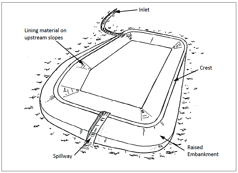
Figure 14-2: Typical Lagoon
Construction is similar to an earth embankment. Excavation and embankment slopes are normally 1 (v) to 2.5 (h). The embankment is constructed in 300mm layers. Compaction can normally be carried out with bulldozers, tippers or other heavy equipment. In general, compaction that allows vehicle access along the working surface is sufficient for the lined structure.
Care must be taken to allow any seepage between the lining and the final ground levels to pass through the embankment. This can generally be done with a 1m x 1m hardcore/ballast filled drainage trench.
The drainage trench can also be used to pass any offtake pipes through the wall.
Considerable care must be taken where offtake pipes pass through the lining. Concrete anchors and bolted flanged connections are preferred.
Considerable care must be taken when securing the lining around the crest of the lagoon. This is normally done with a 50cm x 50cm trench. The lining is placed in the trench and then the trench is backfilled. During the initial filling, the lining should have sufficient slack to allow for any settlement in the embankment. This can be done by securing the lining in the trench with a sandbag every 6m.Once the lagoon has been filled for several weeks, the trench can be backfilled properly and the lining will be securely fixed.
14.3.10 Equipment
Lagoons are generally constructed with mechanized equipment. The following equipment is required:
- Bulldozer (For excavation, trimming slopes and spreading embankment material);
- Loader (for loading tippers);
- Tippers (transport of excavated material to embankment or to spoil, at least two usually four or five);
- Water bowser (for watering material as it is spread and placed in embankment, can be done with hosepipe and existing water supply on many farms);
- Grader (for trimming slopes and spreading embankment material);
- Roller (for compacting material in embankment, not necessary but preferred).
14.3.11 Construction Supervision
- Construction supervision should be most intensive during the initial site layout. Once laid out weekly visits to ensure that the design is being followed should be sufficient.
- Competent small contractors can usually shift 300 to 700 cubic meters of soil per day. Larger contractors may shift up to 1,000 cubic meters of soil per day.
- Supervision of lining placement is important to ensure that all seams are properly welded and that all offtake pipes are properly positioned.
14.3.12 Operation and Maintenance of Lined Lagoons
The main problems encountered with lined lagoons are:
- Torn or damaged lining;
- Algae blooms;
- Blistering of lining material.
Torn or damaged lining material requires that the lagoon be emptied, the tears and damage be identified and then repairs carried out. Welding LDPE or HDPE lining requires that all surfaces are dry. It should be noted that large tears or leaks may endanger the lagoon embankment and that if a significant tear or leak is suspected, the lagoon should be drained as quickly as possible. Any wildlife or livestock that enters a lagoon will damage the lining as it struggles to get out. Access to the lagoon must be rigidly controlled with fences and locked gates.
Algae blooms have been noted in many shallow horticulture farm lagoons. This is partly due to the temperature of the stored water (the black lining helps warm the water) and to fertilizers in some of the runoff water. They can be controlled by introducing fish, adjusting pH or with the use of other chemicals.
Blistering of lining material is usually a sign of excessive seepage between the ground surface and the lagoon lining material. It can be addressed through interception drains uphill from the lagoon or by improved drainage under the lining. Improved drainage under the lining will require that the lagoon be emptied and the lining removed while the drains are installed.
14.3.13 Rehabilitation of Lined Lagoons
Rehabilitation works will mainly concentrate on replacement of lining and filling in any eroded embankments. During rehabilitation works, improved drainage can be installed under the lining.
15 Design of Sand Dams
Sand dams are structures (usually mass gravity walls) that are constructed in a watercourse and are designed to retain both sand and water. When properly designed and constructed, the reservoir area will be filled with coarse sand and water will be stored in the voids between sand grains.
Several manuals address sand dam design and construction in detail and are relevant to sand dam projects in Kenya. “A Practical Guide to Sand Dam Implementation” by the Rainwater Harvesting Network is available online. “Building Sand Dams: A Practical Guide (Madrell & Neal, 2013) is also available online.
Sand dams are most appropriate in areas with high evaporation rates. They are always located in watercourses. An ideal sand dam site is a seasonal river with solid rock bars running perpendicular to the water course. River banks should be rocky material and the banks should be quite deep (at least 2 meters and possibly up to 3 or 4 meters). The lagga must have a heavy sand load when it is in flood. The slope of the lagga bed upstream of the site should be shallow (so that the sand will fill a large distance upstream of the sand dam).
The construction of a successful sand dam is heavily dependent on proper site selection. Before undertaking a sand dam project, it is highly recommended that a successful sand dam be visited. Many NGOs in Kenya have implemented intensive sand dam campaigns in Kajiado, Kibwezi and other suitable areas and will often assist with technical or community visits to discuss and demonstrate what makes a good sand dam site.
Sand dams offer a viable water storage alternative in arid and semi-arid areas where surface water reservoirs or the construction of small earth dams might not always offer the most appropriate solution. This may be due to a variety of reasons including topographic conditions, availability of suitable construction material within an affordable distance from the dam site and high evaporation rates.
15.1 Introduction
A sand-storage dam impounds water in sediments caused to accumulate by the dam itself.
The general principle of a sand-storage dam is illustrated in Figure 15-1. By the construction of a weir of suitable height across a riverbed, sand carried by heavy flows during the rainy season is deposited upstream of the weir, and the reservoir fills up with sand hence creating an artificial aquifer. This aquifer is replenished during the rains, and water for use during the dry season is stored. The weir must be built in stages of approximately 0.3 - 0.5 metres each and allowed to fill with coarse sand before the next stage is built. Failure to do this will result in the reservoir area filling with fine silts rather than coarse sand. Fine silts will not store appreciable amounts of water and will result in a failed project.
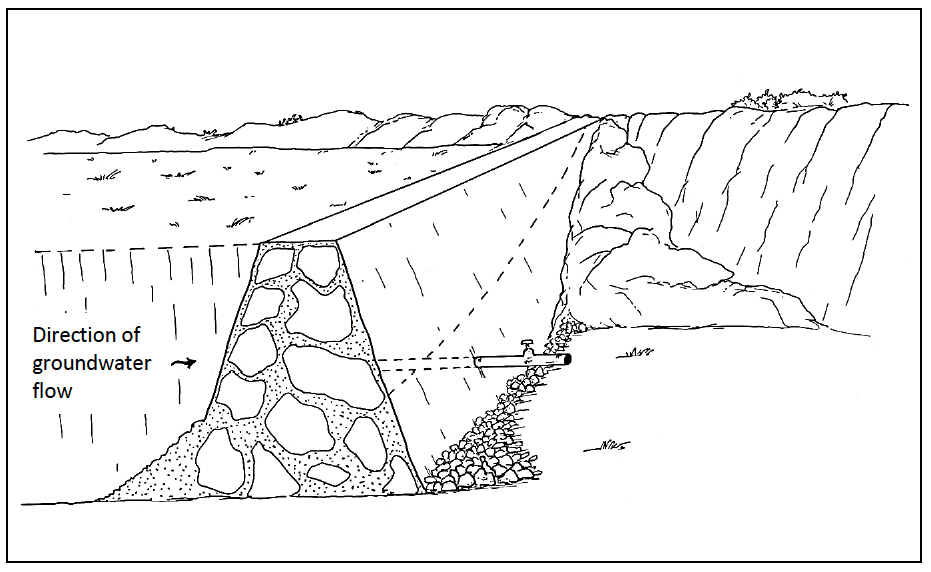
Figure 15-1: Typical Sand Dam
The main advantage of using sand dams instead of conventional dams is a considerable reduction of water losses through evaporation, which is particularly interesting in arid and semi-arid areas. According to Nilsson evaporation from a fine sand storage structure is 50% of that from an open water surface. When keeping the water level at 0.6 m depth in medium sand, evaporation can be reduced to 10% of the open surface value. The granulometry of the material has also an influence on evaporation losses. Evaporation as a function of particle size obtained by Hellwig (Journal of Hydrology 18-1973) is shown in Figure 15-2.
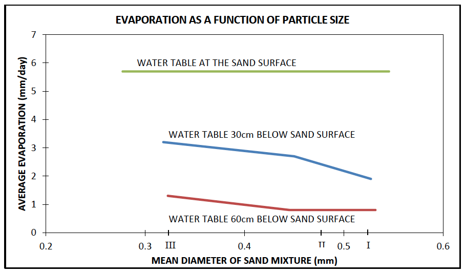
Figure 15-2: Evaporation in Sand Dams
Water stored in sand storage dams is also less susceptible to pollution and less likely to introduce health hazards associated with mosquito breeding.
15.2 Site Selection
Site selection should be considered the most important part of the sand dam project.
15.2.1 Topography/Geology
Topographical and geological conditions determine to a large extent the technical possibilities of constructing sand dams. Storage volumes should be as high as possible, and at the same time dam heights and wall volumes should be kept minimal. The water tightness of the basin in which the water will be stored should be guaranteed. The presence of impermeable bedrock across the floor and both river banks to key the weir into is a pre-requisite for a trouble free sand dam.
The particle size of sediments accumulated in riverbeds is generally proportional to the riverbed slope, whereas depth and lateral extent of the deposits is generally inversely proportional to the slope. The most favourable sites for the construction of sand dams occur when an optimum relation between both factors is achieved. According to Nilsson such sites are most often found on the gentle slopes in the transition zone between hills and plains.
15.2.2 Sediments
The deposition character of sediment influences construction of sand dams in river beds. Sediments originate from parent rocks in the catchment area through weathering and erosion. Coarse sand and gravel particles are desirable in the reservoir. The most favourable rocks are granite, quartzite and sand stone, but also dams constructed in gneiss and mica-schist areas have been successful. Areas underlain by basalt and rhyolite tend to be less favourable however.
The total extent of erosion is largely dependent on rainfall intensity, slope and land use. Catchments with steep slopes and little vegetative cover are usually favourable for the construction of sand dams.
When surveying an area to find a suitable site for a sand storage dam, the absence of sand deposits along the river is not necessarily an indication that no such deposits will occur when the dam is built. It could be that such heavy peak flows occur that sand deposition is not possible under natural conditions.
Total rates of erosion in catchments and rates of sediment deposition in (large) dams are generally reasonably well known, but are not directly applicable here, since sand storage dams use only a fraction of the total sediment load. In order to estimate the useful portion of sediment deposit, a particle size analysis of sediment samples can be helpful. Sediment samples for analysis should as much as possible be obtained during the floods.
15.3 Site Investigations
The construction of sand dams is rather inexpensive and straight-forward. However, many sand dams have been unsuccessful due to unforeseen seepage losses through underlying fracture zones, damage due to improper foundation, erosion around the walls etc. It is therefore important to conduct a minimum number of site investigations before the construction of a sand dam is decided.
15.3.1 Desk Study
Existing geological and hydrological reports and papers, together with topographical and geological maps, satellite images (e.g Google Earth) and aerial photographs can yield valuable information in order to specify target locations for field reconnaissance investigations.
15.3.2 Field Reconnaissance
Field reconnaissance is required in order to identify specific potential sites. The field reconnaissance should focus on:
- Establishing the nature of sediments in the water course;
- The size and condition of catchment;
- The condition of the river banks;
- The depth to and nature of bed rock, both on the floor and sides of the water course to ensure a secure and water tight foundation for the wall;
- The longitudinal profile upstream and downstream of the site;
- The cross section of the potential site.
In order to establish the depth to bed rock, test pits can be excavated, making sure to secure the side walls from collapse. Alternatively, a metal rod (e.g. 10 mm diameter round bar with pointed end) can be used to poke into the sand to test for bedrock.
If there is any doubt about the impermeability of the bedrock foundations for the sand dam, the foundation area should be exposed and evaluated for cracks and weathering. An impermeable foundation is required.
Sand deposits should be evaluated. Test pits should evaluate whether sand deposits are homogeneous or layered. Homogeneous coarse sand is ideal. A repeating thick layer of coarse sand with a thin layer of finer sand and silt on top of it also indicates a good sand dam site. Deep deposits of fine sand and silt indicate marginal sites. Samples from the sand deposits should be taken and should be submitted to a laboratory for the following tests:
- Determination of porosity (the ratio of the volume of voids to the total volume of the aquifer);
- Determination of specific yield (the quantity of water that can be extracted from a saturated sand volume, expressed as a percentage of the total volume);
- Particle size analysis.
The tests above can also be carried out in the field with a minimum amount of specialized equipment.
A survey of any other materials which can be used during the construction of the dam should also be carried out during the field reconnaissance (rocks for rubble stone, nearest source of cement, nearest source of water, ballast, formwork, secure storage area, etc.).
15.3.3 Laboratory Soil Tests
Figure 15-3 shows the test cylinder used for measuring porosity and specific yield. Porosity is determined as follows: A test cylinder (capacity > 2000 ml) is filled with 1000 ml of water and sand is added until the sand level reaches the 2000 ml mark. The water level will be higher than the 2000 ml mark. Water is drained from the test cylinder to adjust the water level to the 2000 m1 mark. The volume of the drained water is recorded.
The porosity (%) is calculated as follows:
Equation 15-1:
$\mathbf{P = (V/T)*100}$
Where:
P = Porosity [%] (typically 20 - 35%);
V = Volume of water remaining in the test cylinder [ml] = (1000ml - $V_{drained}$);
T = 2000 [ml]
To avoid air voids in the test cylinder, it is essential to put the sand sample into the water and not the other way round.
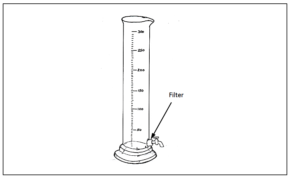
Figure 15-3: Test Cylinder for Measuring Porosity
To determine the specific yield, the test cylinder (capacity >2000 ml) is filled with 1000 ml of water and sand is added until the sand level reaches the 2000 ml mark. The water level will be higher than the 2000ml mark. Water is drained from the test cylinder to adjust the water level to the 2000 m1 mark. This water is discarded. The test cylinder is now drained for 30 minutes and the volume of water released during the 30 minutes is recorded. From this the specific yield is determined as follows:
Equation 15-2:
$\mathbf{S_y = (\frac{V}{T}) \times 100}$
Where:
$S_y$ = Specific Yield [%];
V = Volume of water drained over 30 minutes [ml];
T = 2000 [ml]
A particle size analysis can be carried out as described in Section 9.4.4
15.4 Hydrology
In general, a valley that carries sufficient sand load to justify constructing a sand dam will almost always carry sufficient water to fill the sand dam. Hydrological calculations can be carried out to determine the annual volume of water available for storage and the expected maximum flood at the site. Hydrological calculations are described in detail in Chapter 8 and simple calculations are briefly described below.
A quick estimation of the water available for storage in a sand dam can be made using a 5% runoff factor, the catchment area and annual rainfall as shown in Equation 15-3.
Equation 15-3:
$\mathbf{V = 0.05 \times A \times R}$
Where:
V = yearly runoff volume available for storage [$m^3$];
A = catchment area [$m^2$];
R = annual rainfall [m]
The expected maximum flood can be estimated from Table 15-1 by multiplying the catchment area in $km^2$ times the appropriate Q100 figure given in the table.
Table 15-1: 100 Year Return Period Discharge
| Catchment Area ($km^2$) | $Q_{100} ($m^3$/s/$km^2$) |
|---|---|
| < 1 | 15 |
| 1 - 5 | 12 - 10 |
| 5 - 25 | 3 - 6 |
| 25 - 100 | 3 - 2 |
| 100 - 1000 | 1 – 0.4 |
| > 1000 | < 0.3 |
The broad crested weir formula can then be used to determine expected flood depths (approach heights) upstream of the sand dam/weir. The final sand dam crest level must be positioned so that when the maximum flood passes over the sand dam, the flood is still contained within the river banks. In this case, the crest must be at least “D” meters below the level of the river bank (see Equation 15-5). If this is true, then the expected maximum flood will not result in any “out of bank” flows in the stream bed around and upstream of the weir.
For sand storage dams, the broad crested weir formula can be approximated as shown in Equation 15-4. This equation can be rearranged to solve for the depth of flow and the discharge can be calculated for various flow depths until a flow depth that matches the design flood flow is determined.
Equation 15-4:
$\mathbf{Q = 1.78 \times L \times d^{3/2}}$
Where:
Q = discharge [$m^3$/s];
L = length of the overflow section [m];
d = depth of flow over the weir [m] measured far enough up-stream
A factor of safety is prudent to ensure that the design flood Q can be passed within the overflow section. Equation 15-5 provides an estimate for the final depth of the overflow section.
Equation 15-5:
$\mathbf{D = 1.5d + 0.1}$
Where:
D = Final depth of overflow section [m]
15.5 General Design Considerations
The following items should be considered.
15.5.1 Foundation
Sand dam foundations should be on bedrock, in order to avoid seepage under the dam and for stability reasons. In case the rock formation is weathered, this profile should be completely excavated before the dam foundation is constructed. The presence of open fracture zones should also be investigated. If the presence of fracture zones is suspected, the rock surface should be cleaned and simple infiltration tests carried out by pouring water on the cleaned surface. If fractures are discovered, they need to be sealed, and expensive grouting might be required.
15.5.2 Downstream Aprons
Downstream aprons should be considered if there is any possibility of erosion at the downstream toe of the sand dam. Flow velocities at the downstream toe of the dam can be very high and it might be necessary to construct a concrete apron to prevent erosion. In general a 300mm thick mass concrete apron extending across the river bed and extending downstream a distance equal to the height of the sand dam will be sufficient to prevent erosion in the immediate area of the downstream toe.
15.5.3 Wing Walls
As sand dams are most suited to deeply incised water courses, it is often necessary to ensure that the river banks are protected. This can be done by masonry walls along the banks. For most sites wing walls should be constructed for 5m upstream of the dam and 3m downstream of the dam.
Wing walls should extend a sufficient height above the sand dam sill so that large floods are still contained in the river course and do not cause erosion outside of the river channel.
15.5.4 Storage Capacity of the Reservoir
The (total) storage volume of the dam can be estimated from the geometry of the river bed (see Figure 15-4) using the following simplified formulae:
Equation 15-6:
$\mathbf{SV = \frac{1}{2}H \times L \times W}$
Where:
SV = Storage Volumn [$m^3$](Note: This is total volume, not water volume);
H = wall height [m];
L = length of throw back or fetch [m]
L can be measured or calculated as: = [H x 100] / [slope of riverbed(%)];
W = average width of the reservoir [m]
The expected water yield from the dam can be estimated as:
Equation 15-7:
$\mathbf{Y = \frac{S_y }{100} \times SV}$
Where:
Y = yield [$m^3$];
$S_y$ = Specific Yield (%);
SV = Storage Volumn [$m^3$]
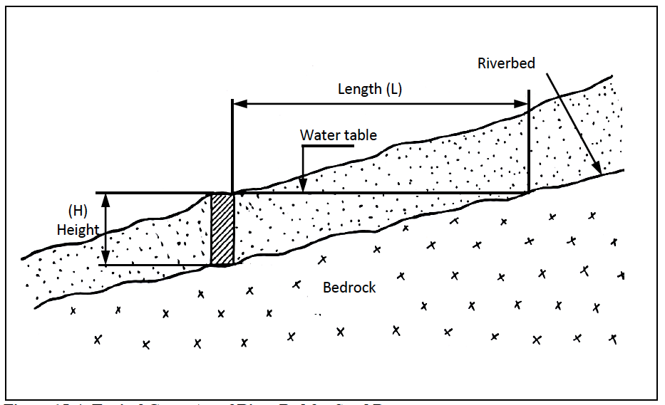
Figure 15-4: Typical Geometry of River Bed for Sand Dam
15.5.5 Types of Walls
The design of the wall for a sand-dam should make use of locally available materials and should meet the following design criteria:
- be sufficiently massive to resist the horizontal pressures exerted on the wall by sand and water;
- provide a water tight barrier against seepage either under or through the wall;
- be sufficiently robust to withstand flood flows over the wall;
- should penetrate sufficiently into the banks with side/wing walls to ensure that flows do not erode the bank and bypass the wall.
The following types of walls are commonly used for sand dams:
- Mass concrete using lean concrete mix;
- Rubble stone masonry wall built with waterproof mortar (1Kg waterproof cement per 50Kg cement).
Gabion walls with artificial lining materials have been used in the past but are no longer recommended.
15.5.6 Dimensioning the Dam
Sand storage dams should be designed for stability against sliding and overturning. Safety factors with respect to sliding ($F_S$) and overturning ($F_{O.S}$) should not be less than 1.5.In general, sand dam heights should not exceed 3 to 3.5m without careful design. Sand dam lengths should not exceed 25 to 30m without careful design.
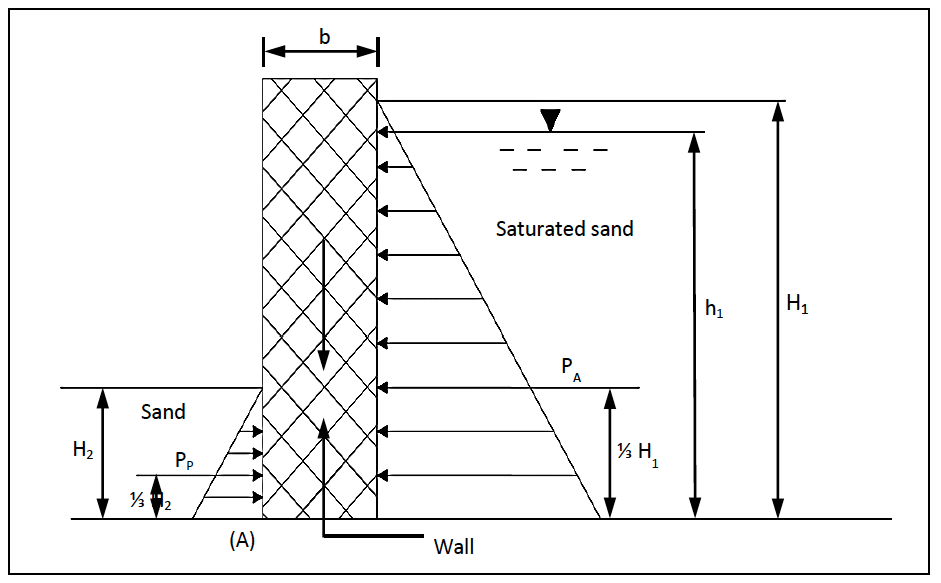
Figure 15-5: Stability Calculations
Figure 15-5 shows an example of a stability computation for a vertical wall. Although the water should not be allowed to rise to the surface for reasons of avoiding pollution, it is assumed that the whole sand layer is saturated (i.e. $H_1$ = $h_1$). Computation of safety factors requires Equation 15-8 through Equation 15-12.
Equation 15-8: Active earth pressures
$\mathbf{P_A = \frac{K_A \cdot w_3 \cdot H_1^2}{2}}$
Equation 15-9: Passive earth pressures
$\mathbf{P_P = \frac{K_P \cdot w_2 \cdot H_2^2}{2}}$
Equation 15-10: Overturning moments
$\mathbf{M_O = \frac{P_A \cdot H_1}{3}}$
Equation 15-11: Resisting moments
$\mathbf{M_r = \frac{P_P \cdot H_2}{3} + \frac{b \cdot F_v}{2}}$
Equation 15-12: Safety factors
$\mathbf{F_s = \frac{r \cdot F_v}{F_h} ; F_{o.s} = \frac{M_o}{M_r}}$
Where:
$K_a$ ; $K_p$ = coefficients of active and passive earth pressure;
$K_A$ = $\frac{1 - \sin\partial}{1 + \sin\partial} ; K_P = \frac{1 + \sin\partial}{1 - \sin\partial}$;
$\delta$ = angle of fricition of the sand [°] (typically 30 - 40°);
$w_2$ ; $w_3$ = unit weights of unsaturated and saturated sand $[kN/m^3]^3$;
$F_v$ = Weight of wall $[kN]^4$;
$F_h$ = Sum of horizontal forces [kN] = ($P_P - P_A$);
R = Friction coefficient $[-]^5$;
$H_1$ ; $H_2$ ; b = Dimensions [ m as indicated on Figure 15-5]
15.5.7 Outlet Works
Outlet works are designed so that water can be drawn from the sand dam in a controlled manner. The main point of having outlet works is to prevent the need for excavation of shallow wells in the sand reservoir area which can lead to human and animal traffic on the sand surface which can lead to pollution of the water in the sand. In addition, shallow wells excavated in the sand reservoir will be destroyed during each flood event. Two alternative arrangements can be considered:
-
Outlet pipe through the wall. This arrangement can consist of a 2 - 3” GI pipe through the wall with a gate valve below the wall. A perforated length placed horizontally at the upstream toe of the wall covered in a ballast surround provides suitable infiltration into the pipe. This option has a number of advantages, including:
- Water is passed through the dam wall, reducing traffic on the sand reservoir;
- Water is drawn by gravity and can be conveyed to a water point, cattle trough or field for use;
- The reservoir can be emptied should the need arise.
The option also has some disadvantages which include:
- The reservoir can be emptied if the flow control is not maintained in good working order;
- A pipe through the wall can introduce a line of weakness for seepage;
- The pipe can get blocked if the inlet arrangements do not provide sufficient protection from debris entering the pipe.
-
Shallow well with handpump constructed upstream of the wall and adjacent to the river bank. This arrangement may require a graduated sand/gravel infiltration drain (1 x 1 m) placed at the river bed level to connect the sand reservoir to the shallow well. A 100 mm dia heavy gauge perforated PVC pipe can be incorporated into the sand/gravel infiltration drain to enhance the capacity of the drain. This option has the important advantage that the water from the sand dam cannot be accidentally released as is the case with an outlet pipe. This option also has some disadvantages which include:
- The handpump requires routine maintenance;
- The handpump and shallow well may be exposed to damage from high floods.
15.6 Typical Drawings
Typical drawings for a sand dam include:
- Layout showing site, offtake position and any other relevant features;
- Cross section of the proposed wall showing offtake if relevant;
- Longitudinal profile of the site, showing wall and crest positions and showing any relevant offtake structures.
Appendix B Type Drawing IX - Standard Cross Sections - Concrete Sand Storage Dams, shows the basic construction details for sand-storage dams built in several stages, with lean concrete (1:3:6 mix) as construction material. An upstream cut-off trench (depth depending on the height of the dam) is incorporated in the dam. As shown in the drawing, PVC water-stop profiles have been incorporated in the joints between the various construction stages.
Examples are also given on how the type cross-sections can be used with vertical shuttering, or with shuttering built from stone masonry. The final overflow section should be dimensioned for the expected maximum flood as detailed in Section 15.4.
15.7 BoQs, Specifications and Reporting Requirements
Sample BoQs and specifications for a sand dam are given on the web site.
15.8 Construction of Sand Storage Dams
Sand-storage dams are commonly constructed in stages (see Figure 15-6). The basic idea is to limit the height of each stage in order to keep a sufficiently high water velocity, so that fine particles are washed out while the coarse particles settle. Each stage is typically 0.30 to 0.50 m in height. Each stage should be filled with course sediments before the next layer is added. This is the main reason why the sand dams must be constructed in stages. It is possible to achieve the construction of multiple layers in one rainy season with careful monitoring of the sediment levels.
It is important to ensure that the stages properly adhere to each other once a new level is constructed. This is done by preparing the existing surface (chipping away loose, weathered material) and using a slightly wetter mortar mix in the joint area. The existing surface can be treated with a cement slurry (1:3) in order to facilitate bonding if required.
The method of constructing the dam by periodically adding a new stage means that construction costs will be higher compared to if the dam was constructed to the full height at once. A method which has been successfully used to avoid having to construct the dam in stages is leaving notches in the dam/wall, so that accumulation of sediments is allowed only up to a certain height. The openings are then filled in in stages as the main reservoir fills with sand. This allows the bulk of the construction costs to be incurred at the beginning of the project. If the method of leaving notches is adopted, the notches should be sufficiently wide to prevent the accumulation of fine sediments (silts, clays) behind the section of wall that rises above the notch level.
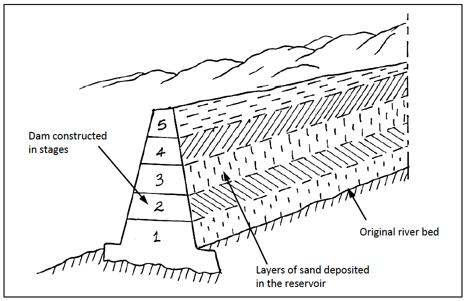
Figure 15-6: Sand Storage Dam Constructed in Stages
A good bond is required between the wall and the foundation rock. In order to achieve this the following steps should be taken:
- All loose rock, dirt, and organic matter should be removed from the rock base;
- The rock surface should be chipped and roughened to remove any loose stone, expose any fissures and to create a key for the wall;
- The rock surface should be swept and cleaned;
- A cement slurry (1:3) should be placed on the rock prior to building the rock surface.
In the event that the rock foundation has steep slopes, it may be advisable to drill and place starter bars into the foundation. This can include the abutments as well. Generally a pattern of 12mm bars placed with 0.5 to 1.0 metre spacing and set 150 to 300 mm into the foundations will be appropriate.
The final wall must protect the river banks from erosion. This can be done by extending the wall into the abutments on either side of the river (5m to 10m on each side may be required) or by constructing wing walls upstream and downstream of the main sand dam. Extending the main wall into the abutments is the preferred erosion protection method as it is generally the least expensive option.
15.8.1 Construction Water Requirements
Water is required for the construction of a sand dam. In the initial stages, it is unlikely that any water will be stored in the reservoir itself so provision must be made for water for mortar/concrete mixing and water for curing concrete and mortar. A small plastic tank can be placed on site to provide temporary water storage during construction. Tanks sizes of 3,000 to 5,000 litres are easily transported on a pickup and can then be filled by a bowser or from existing water sources.
15.9 Equipment
Sand dams can be constructed with manual labour. For larger walls it may be preferable to ensure that a concrete mixer and poker vibrator are available on site. A small pump for dewatering or for pumping water for construction and curing may be beneficial.
15.10 Construction Supervision
Construction supervision can best be carried out by a competent foreman. Engineer visits are usually only necessary during initial site layouts and then periodically to check on progress.
As construction of the complete sand dam wall will usually extend over several rainy seasons, it is preferable to involve local artisans in the construction and to make sure that they can raise the wall level in stages as rains and coarse sand filling allows.
15.11 Operation and Maintenance
Operation and maintenance of sand dams will generally be concerned with ensuring that the top layers of the sand remain coarse and allow water to infiltrate, dealing with erosion or seepage in the area around the dam and with maintaining the offtake structures.
If water infiltration is a concern due to silt/sediment build up on the top sand surface, then the silt/sediment must be removed by raking or digging out. During the next rainy season, coarse sand will backfill where any silt/sediment was removed. Vegetation should not be allowed to grow on the reservoir area.
Erosion or damage to the structure should be monitored and repaired as quickly as possible. Sand bags can be used for temporary fixes, but permanent repairs should be made before the next rainy season. Erosion around the sand dam, reservoir and abutments should also be monitored and repaired as the need arises. This may involve filling in gullies and erosion points with material borrowed upstream or downstream of the structure.
Maintenance of offtake structures may involve digging out the screened inlet areas and removing built up silt. For sand dams equipped with handpumps, spares (U seals, foot valves, handle bushes, etc.) should be kept in stock and used as needed.
15.11.1 Trouble Shooting
Troubleshooting sand dams is fairly straightforward and should cover:
- Outlet problems: For screened outlets, digging out and cleaning screens is the simplest solution. Compressed air can be used to back-flush outlets with some success. For well and handpump outlets, hand pump maintenance and repair should be carried out as needed.
- Sediment problems: When fine sediment build up is problematic, the fine sediments must be manually removed before they have a chance to mix with the coarse sand. If the sand dam is still under construction, consider reducing the stage height for the remaining stages. This will ensure that only coarse sand is captured in each new stage.
- Water quality problems: Poor water quality can be caused by many factors. Pollution by uncontrolled livestock access is a common problem. Chlorination of the sand dam water by digging application pits and applying granular chlorine has proven successful in dealing with biologically polluted water. Chlorine applications must be calculated carefully.
- Height concerns: Sand dams constructed with local artisans should not exceed 3 to 4 meters in height. A series of low dams is often a better alternative than one tall sand dam.
- Construction in layers: Construction must take place in such a way that coarse sand layers are built up. Fine sand and sediments will not store water as efficiently as coarse sand. Determining the best step height or stage height to build for each layer is a matter of judgement, experience and monitoring how sand is deposited. There is considerable trial and error involved.
- Erosion around abutments: Any erosion around the wall can threaten the functional performance of the sand dam and must be remedied properly and urgently. Options include extend the main wall into the abutments or building wing walls along the abutments.
15.12 Rehabilitation
Rehabilitation of sand dams will be required if there are structural problems in the wall or excessive erosion around the structure. It is generally dealt with on a case by case basis.
Rehabilitation of offtake structures (especially wells and hand pumps) may be required at a regular interval.
15.13 NGOs and Capacity Building in Sand Dam Construction
Sand dam construction has been undertaken extensively in the NGO sector as it offers an alternative water storage solutions, and at the same time maintains reasonable water quality while minimising losses through evaporation. A variety of local and international NGOs are actively constructing sand dams in Kenya. Check with county water officers and WRMA officers to see if there are any active programmes in the proposed project area.
Much of the NGO work on sand dams involves building capacity of local artisans. As such, local, trained artisans may be available to assist in proper project implementation.
16 Design of Sub-Surface Dams
The sub-surface dam (sometimes referred to as a “groundwater dam”) is very similar in nature to the sand dam and so the reader is advised to make reference to Chapter 15 on the Design of Sand Dams. The manual “Sub Surface Dams: a simple, safe and affordable technology for pastoralists” by VSF (VSF & TLDP, 2006) details experiences with sub-surface dams (SSDs) in Turkana. In addition, ASAL Consultants have produced the manual “Sub-surface and Sand-storage Dams”. (Nissen-Petersen & Lee, 1990)
The sub-surface dam is distinguished from the sand dam by a number of significant features including the nature of site conditions, outlet options and construction technique. These are elaborated in this chapter.
16.1 Introduction
A sub-surface dam is constructed below ground level and arrests the flow in a natural aquifer, whereas a sand-storage dam impounds water in sediments caused to accumulate by the dam itself.
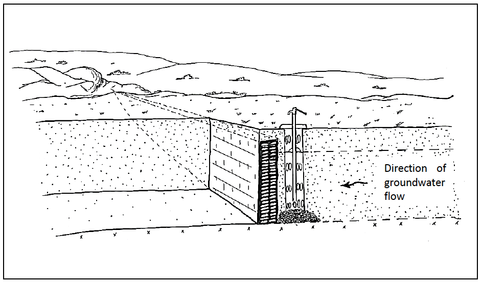
Figure 16-1: Sub Surface Dam
The general principle of a sub-surface dam is shown in Figure 16-1: a trench, reaching down to bedrock, has been dug across a valley, which contains an aquifer consisting of permeable alluvial sediments. An impervious wall has been constructed in this trench which arrests the flow in the aquifer. The impervious wall can be constructed of clay, masonry, gabions (with artificial lining), concrete or a combination of these materials. Excess groundwater will flow above and over the dam crest. In this way, the sub-surface dam does not interfere with flood flows and is not at risk of siltation.
The main advantage of using groundwater dams instead of conventional dams is a considerable reduction of water losses through evaporation, which is particularly interesting in arid and semi-arid areas.
Water stored in sub-surface dams is also less susceptible to pollution and is less likely to generate public health hazards such as breeding grounds for mosquitos.
16.2 Site Selection
Sub-surface dams are only practical in a very narrow range of sites.
16.2.1 Topography/Geology
The topographical/geological conditions for a sub-surface dam are similar to those of a sand dam. The notable exception is that a sand dam is usually placed where the bed rock is exposed or near to the surface and will normally be located in a deeply incised water course.
The sub-surface dam aims to exploit a rock bar hidden beneath a depth of sand or permeable material in a fairly wide water course with poorly defined shallow banks. In general sub-surface dams are most common where the water course has a shallow gradient which results in sandy sediments accumulated along the entire length of the water course.
The location of a suitable rock bar may be identified through analysis of geological formations visible from aerial photography or satellite imagery. Alternatively, the rock bar would need to be identified by probing during field surveys.
Resistivity testing equipment (as used for groundwater exploration) can be used to aid in locating rock bars.
16.2.2 Sediments
The nature of sediments suitable for sub-surface dams is similar to those described in Section 15.2.2 for sand dams. In general river courses containing at least 1m of coarse sand are considered appropriate. Coarse sand has large voids for storage of water from where up to an average of 30 % specific yield can be achieved. Table 16-1 shows specific yield values for a variety of materials that might be found in a sub-surface dam reservoir area. Specific yield is the percent of the reservoir volume that can be used for storing useable water.
Table 16-1: Specific Yields for Various Materials Found in Sub-Surface Reservoirs
| Specific yield % | |||
|---|---|---|---|
| Material | Maximum | Minimum | Average |
| Coarse Gravel | 26 | 12 | 22 |
| Medium Gravel | 26 | 13 | 23 |
| Fine Gravel | 35 | 21 | 25 |
| Gravelly Sand | 35 | 20 | 25 |
| Coarse Sand | 35 | 20 | 27 |
| Medium Sand | 32 | 15 | 26 |
| Fine Sand | 28 | 10 | 21 |
| Silt | 19 | 3 | 18 |
| Sand Clay | 12 | 3 | 7 |
| Clay | 5 | 0 | 2 |
(Source: Johnson (1967) as quoted by CW Fetter)
The deposition character of sediment influences construction of sub-surface dams along water courses. Sediments originate from parent rocks in the catchment area through weathering and erosion. Coarse sand and gravel particles are desirable in the reservoir. The most favourable rocks are granite, quartzite and sand stone, but also dams constructed in gneiss and mica-schist areas have been successful. Areas underlain by basalt and rhyolite tend to be less favourable however. Riverbeds with salty rocks or saline water should not be considered for sub-surface dams.
Catchments with shallow slopes and little vegetative cover are usually favourable for the construction of sub-surface dams.
16.2.3 Traditional Water Holes in Riverbeds and Riverine Vegetation
Sections of river beds with seasonal or perennial waterholes are a good pointer to the presence of natural dykes in the immediate downstream area. Such holes are reliable water sources during the dry season and settlements can often be seen in such areas. In addition, sections of river beds suitable for sub-surface dams can also be identified by observing water-indicating vegetation (see Table 16-2).
Table 16-2: Typical Tree Root Depths
| Botanical name | Depth to water-level |
|---|---|
| Cyperus rotundas | 3 m to 7 m |
| Delonix elata | 5 m to 10 m |
| Grewia | 7 m to 10 m |
| Markhamia hildebranditi | 8 m to 15 m |
| Hyphaene thebacia | 9 m to 15 m |
| Borassus flabellierfer | 9 m to 15 m |
| Ficus walkefieldii | 9 m to 15 m |
| Ficus natalensis | 9 m to 15 m |
| Ficus malatocapra | 9 m to 15 m |
| Gelia aethiopica | 9 m to 20 m |
| Piptadenia hildebranditi | 9 m to 20 m |
| Acacia seyal | 9 m to 20 m |
16.3 Site Investigations
Detailed site investigations are essential to the identification, assessment and selection of suitable sites for sub-surface dams. Key issues to be addressed during site investigations include:
- Presence of firm water tight bedrock formation on which to position the wall;
- Presence of suitable alluvial sediments with high porosity and yield characteristics;
- Water tightness of the water course;
- Water level within the alluvial sediments;
- Access to site for construction.
16.3.1 Desk Study
Aerial photos and satellite imagery, combined with geological maps and reports can help to identify geological formations that may yield suitable sites for sub-surface dams.
16.3.2 Field Reconnaissance
An essential part of the field reconnaissance for sub-surface dams is to establish the cross section and longitudinal profile of impermeable layers along the targeted length of the water course. These topographical features cannot be readily seen and so must be established through topographical survey and probing techniques.
The presence of dykes can be confirmed either by digging trial pits or probing with iron rods hammered into the sand or by use of VES equipment. Alternatively, having a hybrid by combining either two of the methods can improve reliability of the results.
Probing centreline of Lagga: Probing helps to determine the sub-surface profile of the lagga. In an area showing potential for water storage in the sand river, probing is done to try and identify possible natural dykes. Probing is usually done downstream of existing traditional scooped wells in the riverbed as they indicate a sub-surface obstruction that causes water to be retained in the riverbed. Such a sub-surface dyke would form the basis for a sub-surface dam, thus raising the level of water in the sub-surface sand storage reservoir. Probing is also done upstream to find the deepest points in the sub-surface sand reservoir and to determine the extent of storage. Water from the sub-surface reservoir is ideally extracted from the deepest points. Thus, the investigation of a site starts with probing along the centreline over a length of roughly 400 m (200m downstream; 200m upstream of the point identified). The topographical survey of the ground levels of the area being probed is also done to show the surface topography of the area as well as the levels of the riverbanks and surrounding areas.
Probing sections across river for potential dykes and galleries: Where analysis indicates potential sites for a sub-surface dam, probing is done on the section across the riverbed. This is to follow the possible dyke and to determine the dimensions of the sub-surface dam to be designed. Probing is also done across the deep points identified where galleries may be built to extract the water from the riverbed. With potentially large volumes of water stored in the sandy riverbeds, there is a possibility for identifying sections for more than one gallery and/or shallow well for each sub-surface dam.
Confirmation probing: Confirmation probing is done in close proximity to the sections identified for construction of sub-surface dams and galleries. This is done 5m to 10m upstream; and 5m to 10m below the initial section probed. Analysis of the results obtained from the confirmation probing enables the selection of the optimum site for the sub-surface dam; it also enables the selection of the most appropriate site for the gallery and shallow well.
After determining the presence of sub-surface dykes or impermeable layers, test pits should be excavated along the targeted length of the water course to establish the homogeneity of the soil profile across and along the water course.
If there is any doubt about the impermeability of the bedrock foundations for the dam, the foundation area should be exposed and evaluated for cracks and weathering. An impermeable foundation is required.
Aquifer material should be evaluated. Test pits should evaluate whether the aquifer is homogeneous or layered. A homogeneous coarse aquifer is ideal. Deep deposits of fine sand and silt indicate marginal sites. Samples from the aquifer should be taken and submitted to a laboratory for the following tests:
- Determination of porosity (the ratio of the volume of voids to the total volume of the aquifer);
- Determination of specific yield (the quantity of water that can be extracted from a saturated sand volume, expressed as a percentage of the total volume);
- Particle size analysis.
The tests above can also be carried out in the field with a minimum amount of specialized equipment.
The availability of suitable local materials should be established during the field investigations. This will include the availability of:
- Clay or clayey soil for the wall;
- Rubble stones;
- Water.
A survey of any other materials which can be used during the construction of the dam should also be carried out during the field reconnaissance (nearest source of cement, ballast, formwork, secure storage area, etc.).
16.3.3 Laboratory Soil Tests
Figure 16-2 shows the test cylinder used for measuring porosity and specific yield. Porosity is determined as follows: A test cylinder (capacity > 2000 ml) is filled with 1000 ml of water, and sand is added until the sand level reaches the 2000 ml mark. The water level will be higher than the 2000 ml mark. Water is drained from the test cylinder to adjust the water level to the 2000 m1 mark. The volume of the drained water is recorded.
The porosity (%) is calculated as follows:
Equation 16-1:
$\mathbf{P = (V/T) \times 100}$
Where:
P = Porosity [%] (typically 20 - 35%);
V = Volume of water remaining in the test cylinder [ml] = (1000ml - $V_{drained}$);
T = 2000 [ml]
To avoid air voids in the test cylinder, it is essential to put the sand sample into the water and not the other way round.
Figure 16-2: Test Cylinder for Measuring Porosity
To determine the specific yield, the test cylinder (capacity >2000 ml) is filled with 1000 ml of water and sand is added until the sand level reaches the 2000 ml mark. The water level will be higher than the 2000ml mark. Water is drained from the test cylinder to adjust the water level to the 2000 m1 mark. This water is discarded. The test cylinder is now drained for 30 minutes and the volume of water released during the 30 minutes is recorded. From this the specific yield is determined as follows:
Equation 16-2:
$\mathbf{S_y = (\frac{V}{T}) \times 100}$
Where:
$S_y$ = Specific Yield[%];
V = Volume of water drained over 30 minutes [ml];
T = 2000 [ml]
A particle size analysis can be carried out as described in Section 9.4.4
16.4 Hydrogeology
The most favourable type of aquifer for sub-surface dams is surfacial river beds made up of sand and gravel. In situ weathered layers, and deeper alluvial aquifers have also been dammed with success, although such aquifers generally have smaller storage capacities.
Sub-surface dams are very sensitive to permeability values. Difficulties which could be encountered when a groundwater dam is constructed in an aquifer with fine-grained material are small available water storage volumes and difficult water extraction possibilities, due to low permeability of the material.
Improving the permeability of the aquifer by water jetting the ground upstream of the dam is not economically feasible for the type of water supply under consideration. The same can be said concerning the construction of groundwater dams in fractured hard-rock aquifers using grout curtains.
Groundwater dams are, mainly for reasons concerning the excavation techniques used, best suited for shallow aquifers.
16.5 Hydrology
Although sub-surface dams are filled by and rely on groundwater flows, for dams located in shallow aquifers, an estimate of available water can be made from surface hydrology assumptions. Hydrological calculations can be carried out to determine the annual volume of water available for storage and the expected maximum flood at the site. Hydrological calculations are described in detail in Chapter 8 and simple calculations are briefly described below.
A quick estimation of the water available for storage in a sub-surface dam can be made using a 5% infiltration factor (experience shows 2 to 22 percent as an acceptable range for shallow aquifers), the catchment area and annual rainfall as shown in Equation 16-3. This assumes that the catchment area for the shallow aquifer is the same as the catchment area for the surface catchment.
Equation 16-3:
$\mathbf{V =0.05 \times A \times R}$
Where:
V = yearly volume available for storage [$m^3$];
A = catchment area [$m^2$];
R = annual rainfall [m]
16.6 General Design Considerations
Flood events, even on water courses with shallow gradients, can be turbulent, and can result in the movement of a significant volume of sediments. The sub-surface dam wall is contained primarily within the body of the sediments which implies that the wall design should be based on hydraulic loading only. However, if there is concern that the wall is likely to be exposed to turbulent flows and shifting sediments then the design should consider stability against sliding and overturning (see Section 15.5.6).
Sub-surface dam foundations should be solid bedrock impervious clay or a consolidated murram formation and investigated as outlined in Section 15.5.1.
The (total) storage volume of the dam can be estimated from the geometry of the river bed as discussed in Section 15.5.4 from which the volume of useable water can be estimated using specific yield figures.
In general sub-surface dams are less than 5m deep (below surface level) and less than 50m long.
16.6.1 Types of Walls
The different types of walls which can used for sub-surface dams include:
- Compacted impervious (clayey) soil, with a minimum crest width of 3 m and side slopes of 0.75 (h) : 1 (v). Clay walls have a risk of erosion from groundwater flows. This is especially true if the clay is not fully compacted. In addition, clay walls have a risk of cracking and so should only be used for shallow sub-surface dams;
- Rubble stone masonry wall built with waterproof mortar;
- Mass or reinforced concrete.
The key advantage of using masonry or concrete is that they allow the option to raise the wall above the current river level and turn the reservoir into a hybrid sub surface/sand dam.
Other types of walls that could be considered but are not in common use in Kenya are:
- Ferrocement dams;
- Brick wall;
- Plastic sheet;
- Steel sheet;
- Injection screen.
The use of plastic (HDPE or LDPE) lining material in the construction of sub-surface dams offers the possibility of significant cost savings over traditional methods. At present lining material still requires specialized installation tools and lining materials are prone to damage during installation.
16.6.2 Draw-off Works
A sub-surface dam does not usually lend itself to a gravity piped offtake through the wall. In general, a shallow well, placed upstream of the wall and adjacent to the river bed is the most suitable draw off arrangement.
A graduated sand/gravel drain or infiltration gallery connecting the aquifer upstream of the wall to the shallow well may be required. This will depend on the permeability of the river banks.
The paragraphs below describe the construction of an infiltration gallery and shallow well for use with a sub-surface dam.
Infiltration Gallery: Extraction of water from the sub-surface dam can be via an infiltration gallery laid from the deepest section of the sand reservoir saturated with water, towards the nearest river bank with a shallow well. The excavation for the gallery includes removal of all sand, silts, clay, rocks and other materials as well as the control of the high water table, which may rise in the excavated trench.
The infiltration gallery is constructed of 4 inch heavy gauge PVC piping system with holes punched around the pipe surrounded by gravel with size not exceeding 1.5". After laying the piping system, gravel with size not exceeding 1.5" is placed around the pipe and up to a level of 10cm above the pipe. A plastic liner with thickness of at least 0.3 mm is then laid around the gravel pack to prevent sand filling the spaces between the gravel particles. The trench will be backfilled with coarse sand placed in layers above the infiltration gallery.
Shallow well: The shallow well with an external diameter of 1.55m; internal diameter of 1.25m, will be made of culverts or concrete blocks. Manual excavation will be done at the inside of the ring thus lowering it as a caisson to the required depth. Permeable concrete building blocks or culverts are used up to the elevation of the maximum water level in the sub-surface reservoir. Above this elevation, regular building concrete blocks, or precast culvert rings are to be used.
The cast in-situ or caisson lining shall be continued above ground level to form a head wall. The height of this headwall shall be a minimum of 60cm above the original ground level.
A hole will be excavated in the lower concrete blocks or culverts to enable connecting the permeable PVC pipes to the shallow well. These will be connected at the bottom of the shallow well excavation.
16.7 Typical Drawings
Typical drawings for a sub-surface dam include:
- Layout showing site, offtake position and any other relevant features. As the dam will be covered, it is important that the drawings show accurately where it is positioned and any other relevant details;
- Cross section of the proposed wall detailing final dimensions and materials;
- Longitudinal profile of the site, showing wall and crest positions and showing any relevant offtake structures.
16.8 BoQs, Specifications and Reporting Requirements
Sample BoQs and specifications for a sub-surface dam are given on the web site.
16.9 Construction of Sub-Surface Dams
Ideally, the construction of sub-surface dams should be carried out at the end of the dry season, when there is little water in the aquifer. Flow occurring in the river will have to be pumped out.
The preparation of the foundation should follow the description in Section 15.8 in order to ensure that a secure water tight bond is created between the wall and the foundation bedrock.
Where a clay soil material is being used to build the wall, the soil should be compacted at optimum moisture content (OMC). The excavation and re-filling of the trench can be carried out by labour intensive methods since the depths involved are usually limited (< 5m).
Figure 16-3 shows recommended minimum dimensions for subsurface dams. Sufficient attention should be paid to compaction especially when manual labour is used, and to the contact zone between the dam and bedrock. The use of a key in the rock is recommended.
While sub surface dams have been successfully made with thinner crests and steeper slopes, the dimensions in Figure 16-3 will result in a more stable and robust structure.
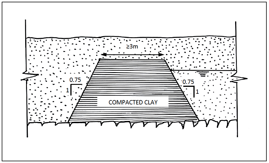
Figure 16-3: Minimum Dimensions for Sub Surface Dams
After completing the excavation, the backfilling should be carried out in stages of around one metre. After filling and compacting the clay dyke, the remaining gap between dam and excavation is backfilled with lightly compacted sand at every stage (see Figure 16-4).
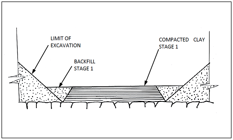
Figure 16-4: Construction Sequence for Sub Surface Dams
Where a masonry or mass concrete wall is to be used, the centre line of the wall should be excavated to a width of 2 meters. The excavation should extend 0.3 to 0.6m into the foundation material and at least 5 to 10 meters into the banks. The wall can be constructed in masonry, rubble stone or concrete. The upstream face should be plastered with 50mm of 1:3 mortar (with water proof cement added at 1kg per 50kg back of cement). The sill of the wall should be brought to the riverbed level. When completed, the upstream and downstream spaces should be backfilled with well watered and compacted material.
16.10 Equipment
Manual labour is usually sufficient for the construction of sub-surface dams. For masonry or mass concrete walls a concrete mixer, poker vibrator and good wheelbarrows will be required.
16.11 Construction Supervision
Construction supervision is essential. The final wall design, alignment and height will depend on what is revealed during the excavations. Having a trained artisan or experienced engineer on site throughout construction will allow the final wall to be tailored to any unforeseen issues that arise.
16.12 Operation and Maintenance
Operation and maintenance of sub-surface dams will generally be concerned with dealing with erosion or seepage in the area around the dam and with maintaining the offtake structures.
Erosion or damage to the structure should be monitored and repaired as quickly as possible. Sand bags can be used for temporary fixes, but permanent repairs should be made before the next rainy season.
Maintenance of offtake structures may involve digging out the infiltration gallery and removing built up silt. For sub-surface dams equipped with hand pumps, hand pump spares (U seals, foot valves, handle bushes, etc) should be kept in stock and used as needed.
16.12.1 Trobule Shooting
Troubleshooting sub-surface dams is fairly straightforward and should cover:
- Outlet problems: For well and handpump outlets, hand pump maintenance and repair should be carried out as needed.
- Water quality problems: Poor water quality can be caused by many factors. Pollution by uncontrolled livestock access is a common problem. Chlorination of the sub-surface dam water by digging application pits and applying granular chlorine has proven successful in dealing with biologically polluted water. Chlorine applications must be calculated carefully.
16.13 Rehabilitation
Rehabilitation of sub-surface dams will concentrate mainly on the offtake structures. Cracks or leakage in the wall will require significant excavations for repairs to be carried out.
17 Design of Rock Catchments
Rock catchments collect water from rock faces and either store the water on the rock face or pipe it to storage tanks located elsewhere. The manual “Manual Number 3 Rock Catchment Dam with Self Closing Water Tap” (Nissen-Petersen & Lee, 1990) provides further reading on design and construction of rock catchments.
17.1 Introduction
Rock catchment dams consist of a concrete or masonry gravity wall constructed around a depression in a rock-surface, so as to retain the water running off this surface. The gravity walls can be any shape or height, and reservoirs of considerable capacity have been created this way. The height of the walls can be either determined by the topography of the dam site or by the expected run-off from the catchment. Gutters or training walls to extend the natural catchment area and to direct runoff along the rock catchment face are often essential to the operation of the rock catchment.
Rock-catchment dams are subject to the same limitations regarding evaporation as earth dams and pans. In order to reduce the evaporation from the reservoir, in certain cases, parts of rock catchment reservoirs have been shaded using a variety of materials including synthetic shade netting. This will not completely eliminate the evaporation but might reduce it by 30 to 40 %.
In order to reduce evaporation and preserve water quality, many rock catchments are now designed to drain into covered tanks.
Due to the nature and size of the catchment areas involved, sedimentation will usually not be problematic in terms of storage capacity reduction. Further reduction of the quantity of silt entering the reservoir can be obtained by fencing off the catchment area (e.g. planting sisal), and by removing soil and vegetation from the catchment before every rainy season. Silt should also be removed from within the reservoir before every rainy season.
17.2 Site Selection
Rock outcrops, presenting a depression or dip, which can be transformed into a reservoir by building either a single (straight) gravity wall, several straight sections of gravity wall or a V or U-shaped gravity wall are suitable sites for rock-catchment dams. Figure 17-1 shows an example where two sections of gravity wall are used to constitute the reservoir. (Sometimes, these dips are filled with soil and need to be emptied first!). No training walls have been used to extend the catchment area. All water is stored on the rock face.
In most cases, even a rock face without any significant natural depressions can be developed with a U shaped gravity wall to allow water collection and storage. Figure 17-2 shows a rock catchment dam on a rock face with a small depression. The proposed wall has been sized to create just enough storage for the expected runoff from a 110mm storm with 80% runoff. Training walls have been used to maximise the catchment area. A pipeline has been provided to allow water to drain (through a sand filter) into a closed tank located some distance away from the catchment. Ideally no water is stored on the rock face.
Choice of a suitable rock face can be confusing. Rock outcrops with vast vertical faces are not suitable for rock catchments as their actual catchment area can be very small. Vertical faces do not collect runoff. Horizontal rock outcrops or outcrops with uniform sloped faces are preferable as they offer the best catchment areas and produce the most runoff.
Rock faces can, in rare instances, be permeable and if possible a quick check can be carried out by pouring water on the rock face and evaluating the runoff. Permeable rock faces cannot be used for rock catchments.
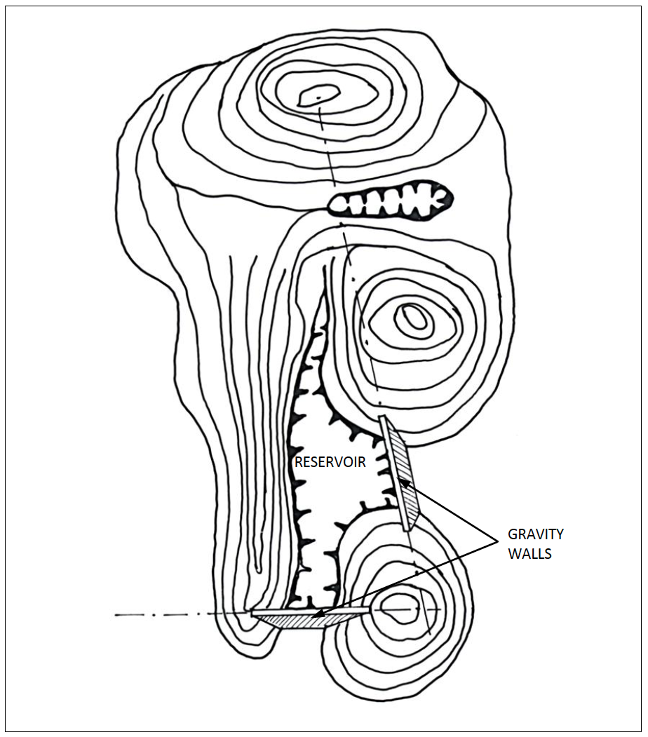
Figure 17-1: Rock Catchment Reservoir on Rock with Depressions
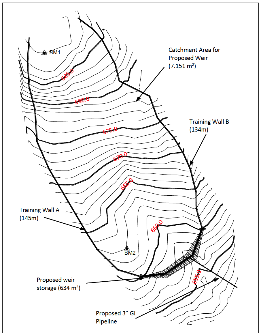
Figure 17-2: Rock Catchment Reservoir on Uniformly Sloped Rock
17.3 Site Investigations
Site investigations should evaluate the extent of the rock face and examine suitable areas for wall construction. If possible judgements should be made as to how hard the rock surface is to work. If possible a topographic survey of the rock face should be carried out as the resultant contour map will allow accurate calculations with regards to gutter placement and length, gravity wall placement, alignment and length and outlet works placement and pipe requirements (See Figure 17-2).
Site investigations should also examine site access, paying special attention to how sand, cement and reinforcement steel can be brought to the site.
17.4 Hydrology
The hydrology for a rock catchment is very straightforward but it depends slightly on the type of rock catchment to be constructed. For a rock catchment where water is to be stored on the rock face, the hydrological calculations should estimate the annual runoff to be collected. For a rock catchment where the water is to be piped to separate storage, the hydrological calculations should estimate an expected maximum runoff volume from a single storm.
In either case, a quick estimation of the runoff can be made using an 80% runoff factor, the catchment area and the expected rainfall as shown in Equation 17-1.
Equation 17-1:
$\mathbf{V = 0.8 \times A \times R}$
Where:
V = volume available for storage [$m^3$];
A = catchment area [$m^2$];
R = expected rainfall [m]
For an annual estimate, the expected rainfall can be the average annual rainfall in meters. For a single storm estimate, the expected rainfall can be the expected storm rainfall in metres. Within Kenya, rainfall intensity maps for a variety of duration and recurrence intervals are available (See Appendix A). If information is not available, then a single storm estimate can be assumed. In most cases an estimated maximum storm in the 100mm to 150mm range can be used but it should be noted that it is an assumed storm value.
17.5 General Design Considerations
The following items should be considered in the design.
17.5.1 Approach
Essentially there are two basic approaches to the design of rock catchment dams:
- Gravity wall provides storage reservoir. The advantage of this arrangement is that there are no further costs related to building storage. One disadvantage of this system is that any seepage through the wall affects the reliability of the water source. Another disadvantage is that the water can become contaminated as it is accessible to both human and wildlife pollution and sunlight which enables algae growth;
- Gravity wall provides temporary flood storage reservoir. In this arrangement the long term water storage is provided by storage tanks situated below and separate to the gravity wall. The advantage of this option is that the gravity wall is only designed to provide storage sufficient for a single design runoff event and the tanks, which need to be water tight and controlled, can be placed at sites which are more suitable for construction and access. The water from this arrangement tends to retain better quality especially if the storage tanks are covered (this also reduces evaporation) and a basic graduated sand/gravel filter is incorporated within the rock catchment offtake works. If the long term runoff volume exceeds the storage tank volumes then additional storage tanks can be added as budget allows.
The selection of design approach is a function of:
- Site conditions: Sites with no pronounced depressions are most suitable to approach (b).
- Nature of water demand: Water for domestic use is most suited to approach (b), water for livestock or wildlife is suited to approach (a).
- Likelihood of contamination of storage reservoir: If contamination appears likely, approach (b) provides better quality water.
- Budget: Approach (b) has higher costs as separate storage tanks are constructed as needed. It does allow the construction costs to be spread over a longer period as all storage tanks do not need to be constructed at one time.
17.5.2 Storage Capacity
In cases where the gravity wall is intended to provide the storage reservoir, the rock-catchment will normally be developed to its maximum capacity. Otherwise the size of the reservoir is to be determined as a function of the water demand and required storage reliability as explained in Sections 3.3 and 8.12.
In order to estimate whether the reservoir can be filled by the expected run-off it is necessary to compute the run-off volume to be expected from the catchment, For the purpose of computing the expected run-off a run-off factor (Kr) of 0.8 is usually appropriate for small rock catchments. The catchment area can in many cases be slightly enlarged by the construction of stone masonry gutters. The possibilities offered by the construction of such gutters depend largely on the topography of the dam site (see Figure 17-3). The gutters are built of flat stones set in mortar as shown on Figure 17-4. The gutter slope should preferably not exceed 2 to 3 % in order to keep flow velocities within acceptable ranges.
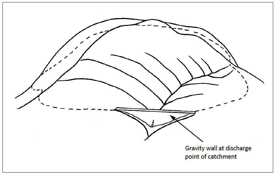
Figure 17-3: Layout of Gutters to Enlarge a Catchment Area
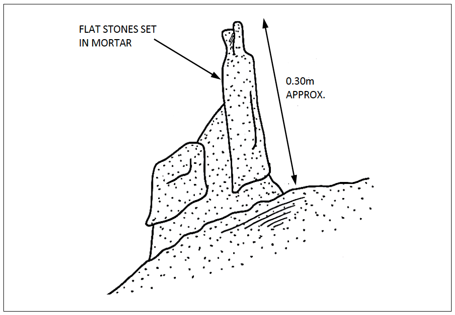
Figure 17-4: Cross Section of Typical Gutters
17.5.3 Design of the Gravity Wall
Gravity walls will be built from mass concrete (1:2:4 mix, not reinforced) or from stone masonry using blocks obtained from natural rock or from rubble stone masonry (hard rock is preferable). The foundation of the wall should be on rock, and the foundation area should be either horizontal or slightly sloping towards the reservoir. It is preferable to anchor the wall at least 0.50 m into the foundation (see Figure 17-5). In order to ensure the water-tightness of the reservoir, special attention should be paid to the contact zone between the rock and the wall. When a masonry wall is used, it should be plastered (20--30mm) with waterproof cement mortar on the reservoir side.
Wall dimensions should follow typical ALDEV dimensions (see Section 13.4). Wall height should be limited to 3.5m and wall length without buttresses or corners should be limited to 30m.
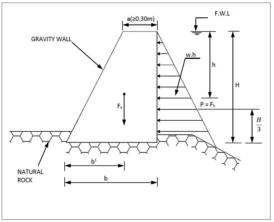
Figure 17-5: Typical Gravity Wall
The wall should be dimensioned to resist water pressure. Stability against sliding and overturning should be verified. The same approach as for sand storage dams or mass gravity walls can be used. The following formulae are now applicable (see Figure 17-5):
Equation 17-2: Hydrostatic Pressure
$\mathbf{F_h = P = \frac{w \cdot H^2}{2}(kN)}$
Equation 17-3: Overturning and Resisting Moments
$\mathbf{M_o = \frac{P.H}{3}; M_r = \frac{b' \cdot F_v}{2}}$
Where:
w = Unit weight of Water = 9.81 kN/$m^3$;
Safety factors with respect to sliding ($F_S$) and overturning ($F_{O.S}$) should not be less than 1.5.
The top width of the wall (a) should not be less than 0.30 m. For walls higher than 2.50m, the top width should preferably not be less than 0.50 m.
17.5.4 Overflow Sections
If properly constructed, the entire crest of the gravity wall can be used as an overflow section and there is no need for a detailed design.
There is also no need for a detailed inflow flood design. The rock catchment is simply designed to fill up and then overtop.
In the event that it is desirable to direct overflow water away from downstream infrastructure or into alternative storage sites, then spillway and inflow design flood calculations must be carried out and appropriately sized diversion channels can be constructed.
17.5.5 Draw-Off System
Draw-off systems for rock-catchment dams generally consist of a perforated GI pipe, laid horizontally at the upstream toe of the gravity wall, surrounded by sand/gravel filter material. The draw-off pipe passes through the gravity wall (diameter preferably 75 mm) to a gate valve located in a valve chamber below the wall. To minimise the risk of seepage along the pipe two or more (welded) steel collars can be provided where the pipe traverses the wall.
Leaking draw-off systems can result in considerable wasted water. Failed valves will result in the rapid emptying of a rock catchment. Whenever possible, redundant valves should be placed in the draw-off system. Other alternative offtake arrangements, such as the self-closing water tap, can be considered.
17.5.6 Storage Tanks and Ancillary Structures
There are various ancillary structures that are commonly associated with rock catchments. These include storage tanks, kiosks and cattle troughs. Standard Ministry designs, bills of quantities and drawings for masonry storage tanks of various sizes (10, 25, 50, 100, 135, 225 m3), water kiosks, standpipes, and cattle troughs are available on the web site.
17.6 Typical Drawings
A rock catchment project should have the following drawings:
- Site layout showing rock face and final water use location;
- Cross section of any gravity walls;
- Longitudinal section of any storage areas.
Examples are given in Appendix B.
17.7 BoQ, Specifications and Reporting Requirements
Sample BoQs and specifications are available on the web site.
17.8 Construction of Rock Catchments
Construction of rock catchments requires planning. As they are normally built in arid environments, care must be taken to ensure that sufficient water is available for both the construction and the curing of any concrete and mortar.
It is essential to ensure that all materials are delivered to the construction site in a timely fashion. Ideally everything should be on site (and transported to the rock face) before construction begins.
On sloping foundations, the use of starter bars is recommended. They can be drilled into the rock face as needed. 12mm bars set 150 to 200mm into the rock face and placed at a 50cm spacing throughout the foundation area have proven to be effective.
Foundations must be cleaned of all loose rock and any fractures should be filled and plastered before construction begins.
Wall and gutter alignments can be marked out with paint or chalk on the rock face.
17.9 Equipment
Site access is normally severely limited and all construction will be carried out by labour intensive methods. Water storage may be required if there is no alternative water source available. If the site allows vehicle access a cement mixer and wheelbarrows will be required.
17.10 Construction Supervision
Once marked out, construction can be carried out by local artisans with an appropriate level of supervision which can focus on specific aspects of construction – setting out, foundations, construction process, and finishes.
17.11 Operation and Maintenance
Operation and maintenance of rock catchments concentrates on repairing cracks in the gravity walls and ensuring that the offtake arrangements are working properly.
For open catchments, it may be necessary to desilt or remove any animal/wildlife waste during the dry season.
17.11.1 Trouble Shooting
If the rock catchment does not fill, even during average rainy seasons, then the catchment area must be extended with guttering.
If the rock catchment fills and then empties, all fractures and seepage zones in the rock and wall must be filled and plastered.
If poor water quality is a common problem, then piping the water to covered storage tanks should be considered.
17.12 Rehabilitation
Rehabilitation of rock catchments will consist of repairing large leaks and upgrading offtake systems.
18 Ancilliary Structures
The ancillary structures needed for a particular water storage project will be site specific. This chapter presents guidelines for the design, operation and maintenance for a variety of ancillary structures that commonly occur with storage structures. Material from this chapter is drawn from standard ministry (MWIS) designs and WSTF (2011). Relevant and available drawings are presented in Appendix B and on the website to this manual. For more detail, additional references that address each type of ancillary structure should be consulted.
18.1 Water Tanks
18.1.1 Design Considerations
The design considerations for a water tank include the following aspects.
-
Tank Capacity
The appropriate size of tank will be a function of inflow and demand (See discussion in Chapter 3 and 8). In a case where the storage tank serves to balance the daily peak demand then the tank capacity should be approximately 50% of the daily water demand. It should be noted that a tank of this capacity cannot be expected to extend reliability of the service beyond one day in the event of a disruption to tank inflow.
Table 18-1 provides tank sizes for which the design and drawings have been prepared by MWIS and WSTF (2011).
Table 18-1: Standard Tank Sizes
Source MWI WSTF (2011) WSTF (2011) WSTF (2011) WSTF (2011) WSTF (2011) Type Circular ground masonry Circular ground masonry Rectangular Ground Masonry 10m High Elevated Steel 6m High Elevated reinforced Concrete Under-ground
(Berkad)Plastic (uPVC) tanks Tank Capacity
$(m_3)$10 20 5 64 20 215 Sizes range from 1001 to 24 $m^3$ 25 25 10 100 25 50 50 150 50 100 60 60 135 225 -
Elevation
The required elevation of the tank will be a function of whether the water is pumped into the tank or flows by gravity and similarly for the outflow. This will determine whether the tank is placed on or near the ground surface or has to be elevated.
-
Materials
The choice of material for the tank is a function of:
- Size and structural requirements;
- Availability of construction materials;
- Cost;
- Foundation conditions;
- Durability against weather, livestock, wildlife and misuse/vandalism;
Plastic tanks have gained popularity in Kenya recently due to their ease of installation, diversity in capacity and relatively lower costs when compared to other conventional storage options. They are also non-reactive and therefore compatible with different water quality types. The tanks can be surface or subsurface, and their capacities range from 100 litres to 24$m^3$. The only main consideration for the plastic tanks would be the foundation/base. This can be constructed from treated wood, concrete or compacted earth. Regardless of the material used, one should be careful to ensure that the surface of the base is as even and level as possible. This will prevent failure and damage to the tank due to localised pressures on or near the base.
-
Roofing/Cover
A roof or cover to a tank is recommended, especially where the water will be used for domestic purposes because sunlight on raw water can induce algae growth and open tanks can be contaminated. Any roof or cover should provide adequate size opening to facilitate access into the tank for cleaning and maintenance. A roof should include mesh covered ventilation pipes to facilitate “breathing” of tank during filling and emptying cycles.
-
Inflow, Outflow and Washout Arrangements
The inflow, outflow and washout arrangements should be carefully considered as these components are generally the most likely to require maintenance and possibly replacement. All valves at or near ground level should be protected in a valve chamber with a lockable lid. The valve chambers should provide adequate space to facilitate the use and replacement of the valves. Float valves should be placed within easy access of the roof hatch to facilitate monitoring, maintenance and replacement as needed. The level of the washout should be placed below the outlet pipe. Finally consideration should be given to the safe disposal of flow from the wash out.
18.1.2 Operation and Maintenance
Operation and maintenance tasks for tanks include:
- Inspect all valves and test function by opening/closing as necessary;
- Service and/or replace any faulty valves;
- Inspection of tank wall, roof and base for cracks and leaks;
- Determine and implement appropriate repair of cracks;
- Observe and record amount of silt accumulation;
- Clean tank of accumulated silt;
- Check washout and observe any signs of erosion related to washout water.
These tasks should in general be conducted at least once per month.
18.2 Stand Pipe/Community Water Point
18.2.1 Design Considerations
Key issues on the design of the standpipe include siting, ensuring the up-stand pipe is firmly secured against regular use, ensure a firm platform at the appropriate height for the water-drawer to place his/her container, stop-cock/gate valve near the standpipe to facilitate repairs of the tap, and the overflow water drains away from the collection point to avoid muddy pools of water impeding access to the stand pipe and creating a potential breeding ground for insects. Any meter should be placed in a secure meter chamber.
The most common problem with stand pipes include unsecure mounting which results in movement of the up-stand which ultimately causes damage to the joints and/or delivery pipe. Other common problems include damage/wear to the tap and inadequate drainage of spilled water.
18.2.2 Operation and Maintenance
Regular inspection of the gate valve, tap and drainage is required. An easily solvable problem like a leaky or non-functioning tap can result in the loss of supply from the whole project. If the stand pipe is within a fenced compound, then inspection and repair of the fence should be undertaken to ensure that uncontrolled livestock cannot cause damage to the stand pipe. The meter, if applicable, should be checked that it is operating properly and read on a regular basis.
18.3 Water Kiosk
18.3.1 Design Considerations
Design considerations for a community water kiosks include:
- Storage and the placement of storage;
- Water-drawing arrangements for pedestrians and, if appropriate donkeys and hand carts;
- Drainage;
- Operator room/office space;
- Security for cash and records;
- Tools and spare parts for kiosk and water supply.
Reference should be made to standard designs and drawings. Improved designs have incorporated an elevated tank (usually plastic) placed on the concrete roof slab of the water kiosk. Such designs are ideal for locations with space restrictions. Typical drawings and reinforcement schedules for this arrangement are provided on the website.
18.3.2 Operation and Maintenance
The key operation and maintenance tasks associated with a water kiosk include:
- Check the fence and repair;
- Check structure of the water kiosk and repair as required;
- Check tap(s) and service as required;
- Check gate valves and meters and service as required. The meter may have a sieve that should be removed, cleaned and reinstalled;
- Tidy kiosk and surrounding area of garbage, litter, and any animal dung.
18.4 Cattle Trough
18.4.1 Design Considerations
When specifying cattle trough dimensions it is important to know approximate herd sizes that will be using the trough and if the trough will be predominantly used by goats, cattle, camels or a mix of livestock.
Standard designs are available for animal troughs which are specific to cattle/donkeys, sheep/goats and camels. Gate valves should be placed securely in close proximity to the livestock trough to facilitate servicing of the ballcock.
The livestock trough should be water tight so careful attention should be made to the foundation conditions (to avoid differential settlement that can induce tension cracks in the walling) and the quality of the plasterwork.
18.4.2 Operation and Maintenance
Operation and maintenance tasks are similar to a water kiosk but particular attention should be given to the structure and any plaster cracks repaired without delay. The ballcock needs servicing (replace pin and washers) and the area around the trough should be inspected for poor drainage. The combination of livestock dung and stagnant water can result in an unpleasant environment.
18.5 Cattle Ramp
18.5.1 Design Considerations
Cattle ramps provide a low cost way to ensure livestock can access the water in a dam or pan. Use of a cattle ramp reduces erosion around the reservoir and contamination of the water reservoir through uncontrolled contact with livestock. However, use of a cattle ramp will diminish the quality of the water making it unfit for human consumption without treatment. If a dam or pan is to be used only for livestock watering, it is not necessary to install any offtake structures.
A 15m wide (or larger) gently inclined cattle ramp can be constructed by placing 300mm of rolled hardcore on a 300mm sand bed for sections above the water line. Below the water level, the surface of the ramp should be protected by a 300 mm rip-rap layer, on an impervious clay blanket where required, which should be covered by gravel (See Type Drawing VI, VII and VIII for details).
18.5.2 Operation and Maintenance
The key maintenance task for a cattle ramp is to ensure that the surface is not covered in sediments thereby providing no advantage over other points of access to the water. Any places where the ramp material is broken up or buried should be covered with new hardcore/rip rap that is firmly secured in place.
18.6 Water Level Gauges
18.6.1 Design Considerations
Water level gauges are useful for estimating the volume of water present in a dam or pan. They can be constructed of metal pipe (usually 2 inch) set in concrete. 3.0m sections of pipe set at least 0.5m into a concrete footing are recommended. Scrap lugs should be welded to the bottom 0.5m of the pipe to ensure that it is securely held by the concrete. Pipes should be painted in 0.5m intervals. Finer intervals can be used for more accurate volume estimations (see Figure 18-1). Longer pipe sections are not recommended as they tend to be more easily damaged or destroyed.
It is advisable for owners and/or users of dams and pans to maintain proper records of regular readings of the water level in the dam or pan.
Careful attention should be given to the datum and zero level for the staff gauges to get the maximum benefit out of the staff gauges. The zero level can be set either at the lowest point in the reservoir or at the mouth of the outlet, in which case the staff gauge will just read the depth of live storage.
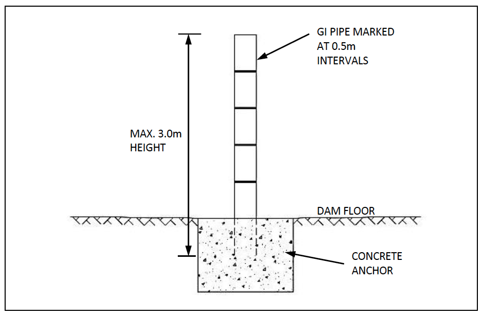
Figure 18-1: Typical Water Level Gauge
18.6.2 Operation and Maintenance
Operational tasks related to the staff gauges include making regular observations of the water level and keeping proper records. The primary maintenance task is to ensure that the markers are legible. The gauge should be repainted whenever required.
18.7 Fencing
Allowing either people or livestock near or in the reservoir increases the risk of polluting the reservoir water. Fencing a reservoir area helps to reduce the risk of uncontrolled access and drowning. Consequently, reservoirs areas should be fenced, and a draw-off system included in their design.
Fencing of dams and pans is, in theory, a very good idea. In practice, with the exception of commercially managed storage, fences very rarely last as long as planned.
18.7.1 Design Considerations
For the type of dams under consideration, barbed wire fencing on wooden posts will usually be adequate. Timber posts to be used for fencing will preferably be well seasoned straight wooden posts of 100 mm to 150 mm of diameter and 2.00 m in length.
The posts shall be firmly embedded 0.6 m deep in the ground. The portion of the posts buried underground should either be encased in concrete or treated against attack by insects.
Strutted straining posts (150mm diameter) should be provided at ends, corners and acute changes of direction or level, and at intervals not exceeding 100m in straight line fence. Struts (100mm diameter 2.40m long) must be secured to the straining posts at an angle of 45°, preferably with a spiked through bird’s mouth rebated joint. Intermediate posts shall be provided at intervals not exceeding 3 meters.
Fences consisting of three or four strands of barbed wire, spaced at 0.30m to 0.40m from each other, will usually be adequate to restrict cattle. All wires shall be strained tight by an appropriate strainer (e.g. ratchet winder) before being attached to the intermediate posts.
In order to minimize interference of the fenced and impounded area with wildlife habitat, it can be desirable to vary fence design so that livestock (and humans) are excluded but wildlife is allowed to pass. Figure 18-2 shows examples of fences which exclude cattle while permitting small antelope to pass under the fence (Note the smooth bottom strand!).
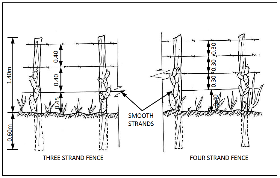
Figure 18-2: Fences for Dams and Pans
The use of live fences composed of thorny bushes should be combined with barbed wire fences. Recommended plants for live fences include Cactus and Sisal, which will deter livestock from entering the dam and reservoir area. Live fences should be planted as soon as the wire fence has been constructed. The selection of plant for the live fence should consider the viability of the plants given the local climate and rainfall pattern. Some live fencing material can be very invasive and while it may serve well as a fence, it may present other problems around the reservoir area.
18.7.2 Operation and Maintenance
Fences will deteriorate and must be regularly inspected and repaired immediately if they are to serve the intended purpose. Live fences should also be maintained which may involve trimming, infilling gaps, and replanting sections as needed.
18.8 Offtakes
There are a number of offtake options for most water conservation structures. The analysis of options is specific to the type and site conditions of the water conservation structure. Detailed design documents should be referred to once a choice of structure has been made. This section provides an overview on various design considerations.
18.8.1 Design Considerations
The design of the offtake structure should consider the following factors:
- Water quality and type of use to which water will be put. This may necessitate the use of specially designed filter and filter media to remove as many impurities as possible;
- Maintaining the water tightness of the water storage structure;
- Pumping or gravity options;
- Risk of emptying the reservoir;
- Accessibility to conduct inspection and maintenance activities. Essentially any offtake structure that is covered or buried should be designed to be robust as accessing the component for repair may not be possible;
- The need for a meter to measure abstraction.
Due to fairly low water quality of stored runoff water, abstraction of water for human consumption should be, wherever possible, through a specially constructed infiltration gallery with a sand or sand-gravel filter as shown on Type Drawing III. The thickness of the filter should not be less than 1.00 m, while its granulometric composition should satisfy the recommended USBR filter criteria (United States Department of the Interior - Bureau of Reclamation, 1987). Filters that incorporate a geotextile layer are possible but are not commonly used in Kenya.
In areas where it is not desirable to pass an offtake pipe through the wall of a storage structure (dam, sand dam), an offtake well can be constructed. The well can be linked to the reservoir via a pipe or via a filter drain as shown in Type Drawing VIII. The well should be lined and water can then percolate into the well through a filter ring made of no-fines concrete as indicated in Type Drawing VIII. The well should be located in a convenient place, preferably away from any inlet structure and cattle ramp. The well can be equipped with a hand-pump. Detailed references for the design of shallow wells and selection of hand-pump type should be consulted.
This structure has the advantage of avoiding any possibility of draining the reservoir through careless operation of valves.
In lined lagoons and pans where water is removed by pumping, it is often common to use submersible pumps (usually a borehole pump positioned inside a large diameter “sleeve” to avoid damaging the lining). It is also common to use floating pumps (usually a small raft with a walkway access) connected to supply pipelines via a section of flexible pipe.
Preliminary offtake pipe sizing can be done based on required discharge rates.
Table 18-3 on the following page gives low, average and high discharge rates for a variety of uPVC and GI pipe sizes. The discharge rates are based on flow velocities where low flow rates are determined using a velocity of 0.5 m/s velocity, average uses 1.0 m/s and high flow rate uses 3.0m/s.
Table 18-2: Typical Offtake Pipe Flow Capacities
| Pipe Size | Pipe Diameter and Class | Low Flow | Avg Flow | High Flow | |
|---|---|---|---|---|---|
| Inch Size | (mm) | $m^3/hr$ | $m^3/hr$ | $m^3/hr$ | |
| 12" | 315 | 315mm D | 113 | 225 | 676 |
| 315mm E | 107 | 213 | 640 | ||
| 10" | 280 | 280mm D | 89 | 178 | 533 |
| 280mm E | 84 | 168 | 504 | ||
| 8" | 225 | 225mm D | 57 | 115 | 344 |
| 225mm E | 54 | 109 | 326 | ||
| 6" | 160 | 160mm C | 30 | 60 | 180 |
| 160mm D | 28 | 56 | 169 | ||
| 160mm E | 26 | 53 | 159 | ||
| 4" | 110 | 110mm C | 14 | 28 | 84 |
| 110mm D | 13 | 27 | 80 | ||
| 110mm E | 12 | 25 | 75 | ||
| 3" | 90 | 90mm C | 9 | 19 | 56 |
| 90mm D | 9 | 18 | 53 | ||
| 90mm E | 8 | 17 | 50 | ||
| 2.5" | 75 | 75mm C | 7 | 13 | 39 |
| 75mm D | 6 | 12 | 37 | ||
| 75mm E | 6 | 12 | 35 | ||
| 3" | GI | 3inches | 8 | 16 | 48 |
| 4" | GI | 4inches | 14 | 28 | 85 |
| 6" | GI | 6inches | 32 | 64 | 191 |
| 8" | GI | 8inches | 57 | 113 | 339 |
For offtakes that use a perforated or slotted offtake pipe, it is useful to be able to quickly estimate the perforated or slotted area required to achieve design discharge rates. If velocities in the screen are restricted to 0.025m/s, then Equation 18-1 will give a figure for the required open area in the offtake screens. This can then be used along with perforation size and positions to determine a length of perforated or slotted pipe.
Equation 18-1:
$\mathbf{A = Q/V}$
Where:
A is the required open area in the inlet perforated pipe [$m^2$];
Q is the desired flow from the dam in [$m^3$/s]
V is the velocity of the flow in the inlet screen and is set at 0.025 [m/s].
18.8.2 Siphon Offtakes
In certain circumstances, siphon offtakes can be used to pass water over the top of an embankment. In many cases they are positioned through the top of embankment walls (normally at the normal water line or just below it). In general the maximum height that a siphon can draw water over is 5.0m. This maximum height is determined by atmospheric pressure and varies depending on the elevation of the reservoir.
Siphons require heavy class pipes (thinner classes are susceptible to crushing) and are also extremely sensitive to friction losses from pipe fittings (especially entrance and exit losses).
A siphon arrangement will require some form of priming mechanism in order to start the siphon process.
Siphon pipe flow velocities are limited as per Table 18-2 and should generally be kept toward the higher velocity ranges.
18.8.3 Operation and Maintenance
The operation and maintenance tasks are specific to the type of offtake structure under consideration. The components of an offtake structure are frequently buried or covered and so are inaccessible. An important consideration is to monitor the quantity and quality of flow through the offtake structure as this can indicate whether the structure is blocked, or flow is impeded in some way and the condition of the material surrounding the offtake structure. For example, very turbid water would indicate that any filter medium is not working, that sediments are reaching the offtake structure, and that siltation in the offtake structure may be a problem.
The typical maintenance tasks are associated with inspection, servicing and replacement of valves, meters, pumps and piping.
18.9 Culverts
Culverts are often required for inflow channels or for outlet channels.
18.9.1 Design Considerations
Where inlet channels and spillways cross roads, the road crossing should be done with properly constructed culverts. Concrete culverts are generally available in 600, 900 and 1200mm diameters. On spillway channels it will usually be necessary to install multiple culverts to handle the expected flows.
Culvert flows can be calculated using the Manning’s equation for flow through a conduit, and can be used to determine the required size of culvert to carry a specified discharge. The required discharges can be determined from runoff estimates of the area under consideration or from design flood estimates in the case of spillway channels.
From the simplified continuity equation:
Equation 18-2:
$\mathbf{Q = vA}$
And from Manning's Equation:
Equation 18-3:
$\mathbf{v = \frac{1}{n}R^{2/3} S^{1/2}}$
Where:
R = $\frac{A}{P}$
Combining the two formulas:
Equation 18-4:
$\mathbf{Q = vA = \frac{1}{n}R^{2/3} S^{1/2} \pi r^2}$
Where:
Q = discharge [$m^3/s$]
R = wetted perimeter [m]
S = slope [m/m]
N = Manning's roughness coefficient
Table 18-3 gives suggested values for Manning’s coefficient for a wide variety of surface materials.
Table 18-3: Values for Manning's Coefficient
| Surface Material | Manning's Roughness Coefficient -n- |
|---|---|
| Concrete - steel forms | 0.011 |
| Concrete (Cement) - finished | 0.012 |
| Concrete - wooden forms | 0.015 |
| Concrete - centrifugally spun | 0.013 |
| Corrugated metal | 0.022 |
| Earth, smooth | 0.018 |
| Earth channel - clean | 0.022 |
| Earth channel - gravelly | 0.025 |
| Earth channel - weedy | 0.03 |
| Earth channel - stony, cobbles | 0.035 |
| Galvanized iron | 0.016 |
| Gravel, firm | 0.023 |
| Masonry | 0.025 |
| Metal - corrugated | 0.022 |
| Natural streams - clean and straight | 0.03 |
| Natural streams - major rivers | 0.035 |
| Natural streams - sluggish with deep pools | 0.04 |
| Natural channels, very poor condition | 0.06 |
| Plastic | 0.009 |
| Polyethylene PE - Corrugated with smooth inner walls | 0.009 - 0.015 |
| Polyethylene PE - Corrugated with corrugated inner walls | 0.018 - 0.025 |
| Polyvinyl Chloride PVC - with smooth inner walls | 0.009 - 0.011 |
| Rubble Masonry | 0.017 |
18.9.2 Operation and Maintenance
Culverts should be inspected for blockages, any settlement, sediment accumulation, and damage by wildlife and livestock. Excessive sediment would be an indication of insufficient slope.
18.10 Inlet Channels
18.10.1 Design Considerations
For an offline storage structure, it will often be necessary to construct inlet channels to bring flood water to the reservoir. Design considerations include:
- Geometry of the channel. A trapezoidal channel is frequently used as the side slopes are stable, and there is easy access for maintenance and cleaning of the channel;
- Size and longitudinal slope. This is a function of the desired conveyance capacity, material, and topographical conditions;
- Water-tightness and need for lining;
- Control of excess flows. A freeboard and section spillways should be provided to release excess flow at desired locations, where the overflow can be conveyed safely to the water course;
- Handling surface runoff that may introduce unwanted flow and/or debris into the channel. This may necessitate earth embankments on the upper side of a channel to prevent unwanted ingress into the channel.
Lined channels are recommended to minimise conveyance losses. Final lining choices will depend heavily on availability of local materials. A trapezoidal channel such as shown in Figure 18-3 is recommended.
Calculations for flow in trapezoidal channels can be done using Manning’s equation as described in Section 18.9 Culverts.
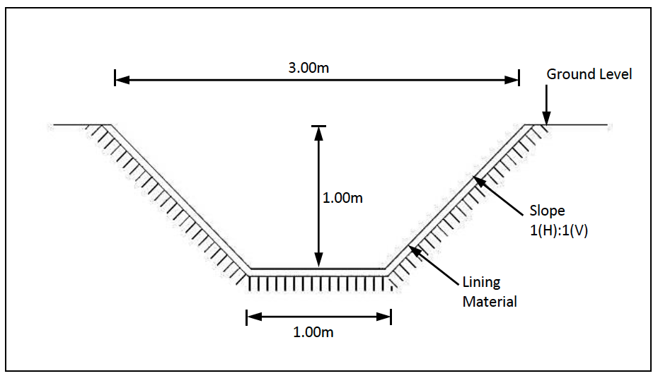
Figure 18-3: Typical Trapezoidal Channel(Section)
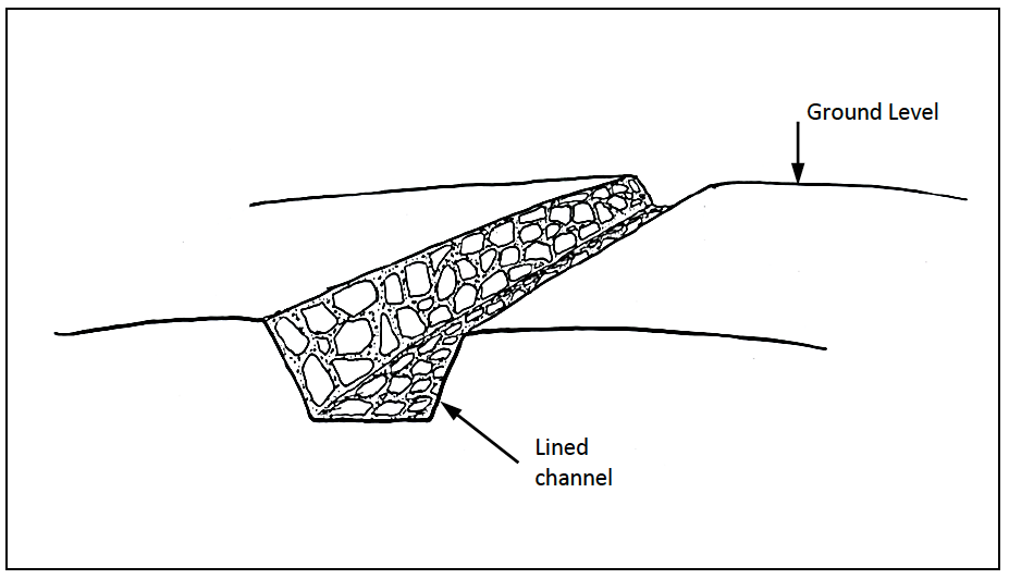
Figure 18-4: Typical Trapezoidal Channel
Channels can be lined with HDPE and LDPE lining material but these must be protected from trampling by livestock. The HDPE and LDPE materials results in a reasonably water tight channel
18.10.2 Operation and Maintenance
Channels should be inspected for blockages, any settlement, sediment accumulation, uncontrolled overflows, and damage by wildlife, livestock, and traffic. Sites showing signs of settlement, sediment accumulation or uncontrolled overflows should be addressed as these are indicators of other issues that need to be addressed, namely a weak foundation, insufficient slope, insufficient freeboard, and excess inflow, all of which can lead to more serious problems.
18.11 Self Regulating Weirs
For reservoirs that rely on river offtakes for inflow, self-regulating weirs can be used to ensure that river water is abstracted strictly in compliance with the water permit and WRM Rules where water is allocated not only by quantity but also by timing in that flood water abstraction can only take place when river flows are in a flood state, i.e. above Q80 (flows that are exceeded 80% of the time).
18.11.1 Design Considerations
A self-regulating weir typically consists of a mass gravity wall across the river. Two openings are left at the top of the weir; one that passes flow downstream and one that flows into a collection box that leads to the conveyance pipe or channel. The river opening is sized and positioned to ensure that at low flows equivalent to the environmental reserve (Q95), all river flow passes through the river opening. The abstraction opening is sized and positioned so that as river flows increase, water begins to pass through the abstraction opening.
The idea is to ensure that the reserve flow is maintained during periods of low river flows and that higher flows are divided appropriately between the river and the abstraction up until the maximum abstraction rate is reached after which all additional river flow passes over the main weir crest and remains in the river channel.
A typical cross section of a self regulating weir is shown in Figure 18-5
Figure 18-5: Typical Self Regulating Weir (Front view)
In general, abstraction should not begin until the river flow reaches the Q95value in order to safe guard the reserve flow. In the section where the flow is above Q80, the width of the opening for the river and abstraction will determine the proportion of the river flow that is going into the abstraction chamber. A guideline value is 50% so that flows are shared equally between the abstraction and river. Once flows exceed the maximum abstraction capacity all the flow will go downstream.
In some instances, mostly where there are other storage structures or offtakes downstream of the self regulating weir, it may be necessary to direct a greater percentage of the flood flow into the river and a smaller percentage into the abstraction opening. This can be done by appropriately sizing the opening widths.
The broad crested weir formulas can be used for sizing openings and determining flows as given in Equation 18-5:
Equation 18-5:
$\mathbf{Q = b \times \sqrt{g \times (\frac{2}{3} \times H_a)^3}}$
Where:
$Q_{max}$ = Discharge over the weir [$m^3/s$]
b = width of the weir [m]
$H_a$ = approach height of the water [m] (measured upstream of the weir)
g = acceleration of gravity [9.81 m/$s^2$]
Note that $H_a$ is equal to $\frac{3}{2} \times H_c$ where $H_c$ is the critical flow depth over the weir.
Various width and approach height options for each opening can be tried until a combination that allows flows as described above is achieved.
Reference can be made to Thomas (2001) for further details
18.11.2 Operation and Maintenance
One of the advantages of the self-regulating weir is that the arrangement of opening sizes and levels means that abstraction is regulated according to the river flows, not by means of opening and closing gate values. However, it is still important to inspect the weir for any cracks and the control valves/gates for wear and/or damage.
18.12 V-Notch Weir
The v notch weir is an example of a sharp crested weir, and is especially useful for measuring low flow rates, because the flow area decreases rapidly as the head over the v notch gets smaller, as would be the case for seepage from an embankment.
Flow over a v-notch weir is calculated using Equation 18-6.
Equation 18-6:
$\mathbf{Q = C_d\frac{8}{15}\sqrt{2g}\tan\frac{\theta}{2}H^{5/2}}$
Where:
Q = flow over the weir [$m^3$/s]
$C_d$ = dimensionless coefficient of discharge
$H_a$ = approach height of the water [m] (measured upstream of the weir)
H = height of water above apex of v notch [m]
For a v notch weir to work effectively, the upstream chamber should be of sufficient length and depth to ensure tranquil flow over the weir.
18.12.1 Design of the V-Notch Weir
Some guidelines when designing a v-notch weir include:
- The centre line of the weir notch should be parallel to the direction of flow;
- The face of the weir should be vertical, not leaning upstream or downstream;
- Water surface downstream of the weir should be at least 6cm below the bottom of the V to allow a free flowing waterfall;
- For accurate measurements, the depth over the crest should not be more than one third the length of the crest.
18.12.2 Operation and Maintenance
Operation and maintenance requirements for the v notch weir would include regular inspection of the blade to ensure that it is upright, regular inspection of training walls and rehabilitation as need arises.
18.13 Break Pressure Tanks
Break pressure tanks (BPTs) are a useful component of a water reticulation system for sections of the system whose pressures exceed the classes of the pipeline installed. As the name suggests, the main function of a BPT is to keep flow pressures within the design limits. The tank may be elevated to generate downstream flow.
18.13.1 Design Considerations
The volume of the BPT should be large enough to give a retention period of up to two minutes. The inlet should end close enough to the floor of the tank to prevent trapping of air from the falling jet of water.
Typical BPT drawings are provided on the website.
18.13.2 Operation and Maintenance
Operation and maintenance requirements would include regular desilting, inspection and repair of pipe connections and valves as the need arises.
18.14 Pump Stations
For pumped distribution systems, a typical pump station should be included. Its function will be to house the controls, switches, pump and motor (in case of a surface pump) and standby spares and equipment. The pump house should be designed to allow for access to serviceable parts, as well as allow for sufficient ventilation and provide adequate security.
Drawings of a typical pump house are provided on the website.
18.15 Water Treatment
This section presents simple water treatment methods that can be adopted at the household level. Treatment options for bulk water can be obtained from the Water Supply Manual (Ministry of Water and Irrigation, 2005).
18.15.1 Boiling
This is the most commonly used household water treatment method. It involves raising the water temperature to 100°C to kill off microbial pathogens. However, the cost of fuel would be an impediment to this choice of treatment, as well ask the risk of burning (UNICEF, January 2008).
18.15.2 Chlorination
This is another common low cost water treatment solution. It involves the addition of Sodium Hypochlorite to the water for disinfection. This method offers a quicker option when compared to boiling, and has fewer cost implications (UNICEF, January 2008).
18.15.3 Filtration
Filtration kits have been scaled down to units that can be used at the household level, and are typically ceramic or slow sand filters. The benefits of using these include improving the aesthetic value of the water and providing treatment without affecting the taste of the water. Filters treated with bacteriostatic silver have been documented to remove at least 99% of protozoa and bacteria.
18.15.4 Solar Disinfection
Also known as Sodis, this alternative option for water treatment involves bottling the water in 2 litre clear plastic bottles and exposing these to UV radiation by placing the bottles on rooftops for 6 to 48 hours, depending on the intensity of insolation. This method has been shown to be effective in reducing microbial pathogens in drinking water (UNICEF, January 2008). However, this method is only effective for low turbidity water.
18.15.5 Combined Flocculation and Disinfection
This method can be adopted for high turbidity water and will involve addition of flocculants such as alum to settle the suspended matter, as well as a disinfectant to kill off pathogens. Products such as PUR have been developed to provide low cost, household level solutions for the treatment of water with turbidity. These can be easily obtained from retail outlets or local pharmacies.